Continue to Site

Welcome to our site!

Electro Tech is an online community (with over 170,000 members) who enjoy talking about and building electronic circuits, projects and gadgets. To participate you need to register. Registration is free. Click here to register now.

  • Welcome to our site! Electro Tech is an online community (with over 170,000 members) who enjoy talking about and building electronic circuits, projects and gadgets. To participate you need to register. Registration is free. Click here to register now.

Shoe Box Radio Upgrade, cool ideas wanted

Status
Not open for further replies.
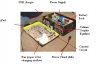
As you can tell by the title, I have a shoe box radio that is in a significant state of disrepair (this is the first time in months that I have taken it out). So to fix this problem, I intend to put the Amplifier (with the radio) in a new housing, one made out of wood and a little sturdier.

While I was at it I figured that I would upgrade the control circuit to something a little more advanced and reliable. To start, the power supply is going to be upgraded from a cheap little power supply made from Radio Shack parts, to something more sophisticated made from parts from Radio Shack. :p

The control circuit is a cheap little circuit that I hastily put together. Now I will remake the entire circuit so that it is more organized and will last longer (due to the neglect in focus when I made it, the relay that works the fan is being "over used")

Some of the ideas for my new circuit are as followed:
1) A fan that has 4 different control positions (the old one only had 2)
2) A power supply that has push button switches
3) I temperature limited fan for the power supply (because the fan makes so much noise!)
4) A heater set to ~25*F (-3.89*C)
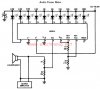
5) An LED VU meter using LM3915 (or something cheaper)

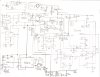
I would also like to throw in Audioguru's FM transmitter to send the signal out to a more powerful radio that may be close buy. I just need to know a little more about it first (I'm reading through the thread)

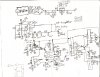
I went ahead and include the schematics that I have completed so far below, I still have a few more... non-chicken scratch schematics to make. I will post them as I finish them.

But as I said, any other cool ideas (preferably cheap ones) would be appreciated.

Thanks, Vince Vumeter.gifscan0005.jpgUSB charger.JPG
 

Attachments

  • lm3915..jpg
    lm3915..jpg
    76.3 KB · Views: 955
What is a shoebox radio?
Ditto.
LM2902 has open collector outputs, and cannot drive LEDs as you have them connected.
I have no other comments, because I have no idea what you are trying to do.
A Google search for shoebox radio yielded multiple hits for Barenaked Ladies.
 
Ditto.
LM2902 has open collector outputs, and cannot drive LEDs as you have them connected.
I have no other comments, because I have no idea what you are trying to do.
A Google search for shoebox radio yielded multiple hits for Barenaked Ladies.

That's um... intresting...

But none the less, wrong. A shoebox radio is exactly what it's name implies, it's a radio in a shoebox due to lack of better building materials or time. The current state of the radio is in a severe state of disrepair, which is why I have decided to upgrade it.

I took the origonal radio appart so that I could fix the casset deck in it, and realised how much extra/ unused space their was inside. So I put it in a shoe box to make better use of the space, but being a black shoebox, it had a tendency to get hot outside, so I put a fan in. Then I thought "how can I make this better?" And I kind of got caried away from their...

I have the circuit for the new power supply done, when I get to a computer with a scanner, I will upload it (the new power supply is more complicated than the entire old circuit together).

I have also though of somethings that I want to add;
1) a remote control (about 4 channels)
2) a 32 pin connector to connect to an iPod so that the remote can work the iPod functions.
 
You are using extremely old ICs and have an old (cough, choke) cassette player? I haven't used my cassette player for about 15 years.

Where is the heat coming from that you need so many fans?
 
The voltage regulator in the power supplu created a considerable amount of heat, so I had put a small 2 inch fan from the processor of an old computer to cool it. The other fan is used to cool everything in the box (it's a black shoebox and gets hot when left in direct sunlight).

In the new circuit, the small fan will be attached to a simple temperature sensor circuit (ie: 741 op-amp), and I'm still debating on whether or not to add the casset deck or not. I probably won't just because it takes up so much space, and like you said, they're just not used that much any more.

But the entire circuit is being re done, mostly because I have made so many modifications to the origonal circuit, that I don't know if I would be able to fix it should something come loose (plus it's just a sloppy mess). The LM324 isn't that old is it?

Any way, I was wondering about the best way to modify your FM transmiter so that it will work with an audio amplifier. Probably something small like an LM386. I've had problems in the past wiith the output of the main amplifier and the 8 ohm speakers plus any other kind of a load.
 
The 7805 regulator gets too hot because its input voltage is too high and maybe your amplifier ICs are oscillating at a very high frequency.
Or maybe you play acid rock too loud.
The motor in a cassette player draws a high current that will melt the regulator.

The LM324 is the oldest low power quad opamp, about 39 years old.

An audio power amplifier is used with a radio, not with a transmitter.

The output power of an LM386 IC is very low, 0.45W with a 9V supply. Like a cheap clock radio.
 
Paint the box with shiny metal paint so it relects away the heat from the sun.
Reduce the input voltage or increase the output voltage of the regulator so it does not waste so much power getting hot.
Then make a real powerful audio power amplifier not just a little squeaker.
 
A few observations.

In the UK a "shoe box" is a cheap flimsy cardboard box which holds new shoes in the shoe shop.
People have been known to keep all sorts of things in them, their treasured possessions, money (so that the taxman does not see it), whatever.
However the concept of building a radio into such a thing is mind boggling.

While you may have the greatest affection for this radio, I cant help but think that you are polishing a turd.

JimB
Shoeboxes are the same in most of the USA. However, in Pennsylvania, everyone wears wooden shoes, so the boxes may be more substantial.;)
 
SHOEBOX radio my first tought was a crystal radio!
cassette tape deck!! I still have a four track cassette tape deck! much less an 8 track!!
 
The power supply was not included in that schematic, sorry about that. The actual power supply has a 12V regulator with a 24V DC input. The new power supply will be "smarter", it will have rechargeable batteries (MAX712, I love these things), higher current output, a battery monitor (ICM7665), and push button power.

I thought that you might be curious about what it looks like, so I included a picture of what the box currently looks like (in its severe state of disrepair), the schematic of the current circuit, and the schematic of the new power supply.

So what you are saying is that your FM transmitter does not need an amplifier to be connected to the input. Does that mean that I should connect the transmitter directly to the output of the iPod and not from the output of the 386?

Even though the 324 is closed, I'm still going to use it in my circuit. After all there isn't really anything wrong with it.

Shoe boxes are not the best building materials I know, but I wanted to have it ready for when school started, and I wanted it to reflect my electronic capabilities (it's a short list).

Audioguru; the amplifier I did not make, I "stole" it from an old radio. But the amplifier on the board is an LA4108. Here you go: Data Sheet (not much there)

Even if I make the housing a different color, sitting out in the sun will create a little heat, the fan is just a little extra that I thought I'd throw in. I wanted the box to be as self sufficient as possible. There is also a heater going to be installed. And yes, I love this box, and I don't thing that I will ever finish it as long as there is something else I can add.
 

Attachments

  • New Power supply&#46.jpg
    New Power supply&#46.jpg
    936.6 KB · Views: 416
  • Old circuit..jpg
    Old circuit..jpg
    979.1 KB · Views: 600
  • Box pic..JPG
    Box pic..JPG
    33.4 KB · Views: 330
Hey don't feel bad. I built a radio in cat food cans. I'm sure a few guys around here remember it. But it sounds like you are using a pre-made radio. So here's a grand idea. Why not make the radio. It could be very cheap and you won't have to rip out the tape deck. There are some ICs that have complete FM receivers in them. Don't ask about mine as it was all discreet components but the dern thing works great. I swear it out performs my Icom 745.
 
A crystal radio was used 100 years ago! Then there were very few stations so selectivity was not important.
Sensitivity was also not important if it could receive the very high power radio station that was just down the road.

Now, AM radios sound awful and there are many AM and FM radio stations. Selectivity and sensitivity (without overload) are very important.

I have a cheap Sony Walkman FM stereo portable radio. It does not receive lousy-sounding AM radio. It is cheap so it is overloaded by strong local stations so it has an attenuator switch (local and distant) to reduce every signal.

I made an AM radio about 50 years ago. It worked but it sounded as awful as new ones today.
 
Hey don't feel bad. I built a radio in cat food cans. I'm sure a few guys around here remember it. But it sounds like you are using a pre-made radio. So here's a grand idea. Why not make the radio. It could be very cheap and you won't have to rip out the tape deck. There are some ICs that have complete FM receivers in them. Don't ask about mine as it was all discreet components but the dern thing works great. I swear it out performs my Icom 745.

That would be an excellent idea except, the radio I'm using now is more powerful than anything I could possibly make right now. But that is an excellent idea, like I said, the project will never be finished, it will only continue to get more complicated, and more advanced. Any suggestions on what kind I should use? (the speakers are rated for 8 watts) I know I've brought this IC up a couple times, but the LM3886 would probably be where I would have to stop working on it.

Ruptured Ear Drums
 
If the input to the voltage regulator is 24V but its output is only 12V then it is throwing away half the input power as heat.
The Sanyo audio power amp has an output power of almost nothing. Why not use a modern high power amplifier IC?
Were you in jail for the last 20 years?
 
Last edited:
That would be an excellent idea except, the radio I'm using now is more powerful than anything I could possibly make right now. But that is an excellent idea, like I said, the project will never be finished, it will only continue to get more complicated, and more advanced. Any suggestions on what kind I should use? (the speakers are rated for 8 watts) I know I've brought this IC up a couple times, but the LM3886 would probably be where I would have to stop working on it.

Ruptured Ear Drums

Here's a cool one right here, the TDA7000: Title: Single chip FM radio

It doesn't look too hard. I would let Audio guru recommend the audio chip. I've used those 386's and well, mine wasn't real loud.
 
I have first hand experience with the 386, and I agree, it's not very loud.

If the input to the voltage regulator is 24V but its output is only 12V then it is throwing away half the input power as heat.
The Sanyo audio power amp has an output power of almost nothing. Why not use a modern high power amplifier IC?
Were you in jail for the last 20 years?

To answer your question, yes I was. I beat someone up because they said electronics were stupid.

I have an old audio amplifier, a GPX HI2817, I can find the audio amp in that (except their all surface mounts) and that would also give me my IR remote receiver.**broken link removed**

There wasn't anything I could do to fix it, first the iPod dock broke, a bad soldering job made it worse. Then when I finally got my hands on another 32 pin connector, the amp stopped working :( and I can't figure out why!
 
Last edited:
Status
Not open for further replies.

Latest threads

Back
Top