Continue to Site

Welcome to our site!

Electro Tech is an online community (with over 170,000 members) who enjoy talking about and building electronic circuits, projects and gadgets. To participate you need to register. Registration is free. Click here to register now.

  • Welcome to our site! Electro Tech is an online community (with over 170,000 members) who enjoy talking about and building electronic circuits, projects and gadgets. To participate you need to register. Registration is free. Click here to register now.

shift register led sequencer.Did I do this right

Status
Not open for further replies.

adown

Member
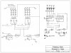
Hi All, I found this circuit from on1aag on a thread that many participated in, but its not quite what I need. I altered it to suit my needs, but I don't know if what I did is right and I'm hoping someone can tell me if it looks like it will work. Also I couldn't read all of his values so I am also hoping to get some help with that. Can I attach Vdd, Vcc and Vss all to the same 13.5 volts. Mine is the computer generated, his is the hand written. Thanks for the help, adown
 

Attachments

  • sch3.jpg
    sch3.jpg
    358.5 KB · Views: 213
Vcc and Vdd possibly since they are both a positive voltage supply depending on the voltage requirements of the components they are powering. BUt not Vss since that's ground.

This is the pairing:

+Vdd
-Vss

+Vcc
-vee
 
Last edited:
Yes Vss is gnd. Stoopid question. Both my components are labed the same Vdd and Vss, I got Vcc from on1aag's drawing. Trying to turn his drawing into something that works has got me over thinking what I'm doing(not that I know what I'm doing). How about his cap and resistor values? I would like to trigger the 4093 with 13.5 volts to pulse every 1/2 second so the shift register lights all 3 led's and resets in 2 seconds to start over. Any ideas what I need to make them work. anyone. Thanks adown
 
Last edited:
Status
Not open for further replies.

Latest threads

New Articles From Microcontroller Tips

Back
Top