Continue to Site

Welcome to our site!

Electro Tech is an online community (with over 170,000 members) who enjoy talking about and building electronic circuits, projects and gadgets. To participate you need to register. Registration is free. Click here to register now.

  • Welcome to our site! Electro Tech is an online community (with over 170,000 members) who enjoy talking about and building electronic circuits, projects and gadgets. To participate you need to register. Registration is free. Click here to register now.

Setting up a Ganged rotary switch

Status
Not open for further replies.

stuhagen

Member
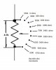
So I am a bit uncertain on what type of switch to get. Each of the 8 detents need to be increments of 600 ohms, *or* compounding. Goal is to have one end outputting '0' ohms and the opposite end outputting approx 4.7k ohms. Each detent needs to decrease or increase by 600 ohms. So I am not sure if I am doing this correct. The resistance determines a certain Freq output. I have a 1-pole 12 position but maybe this is the incorrect switch........
 

Attachments

  • Ganged Set-up.jpg
    Ganged Set-up.jpg
    45.8 KB · Views: 112
If you truly need two independent resistors (4 terminals), then you need a double ganged rotary switch with 8 positions/detents so your 1P12T switch won't work. This should be pretty obvious to wire up since you just wire it up as two independent knobs, except they share the same shaft.

But if those "outputs" are connecting to something that is high impedance and you only need the resistance to be between that output and ground, then you can get away with a 1P8T switch (attached image). If they aren't connecting to something high impedance, you're going to get the two resistances influencing each other.
 

Attachments

  • T-res.PNG
    T-res.PNG
    25.7 KB · Views: 109
Last edited:
If you truly need two independent resistors (4 terminals), then you need a double ganged rotary switch with 8 positions/detents so your 1P12T switch won't work. This should be pretty obvious to wire up since you just wire it up as two independent knobs, except they share the same shaft.

But if those "outputs" are connecting to something that is high impedance and you only need the resistance to be between that output and ground, then you can get away with a 1P8T switch (attached image). If they aren't connecting to something high impedance, you're going to get the two resistances influencing each other.

Your drawing is exactly what I am wanting to do. In essence, I want to replace a regular 4.7K pot that is a continuous sweep with specific levels of resistance. The "output" of each resistor (or total of) is the same as the pot wiper that feeds into a LM358N *NOT* to a ground. Will your drawing work with this single pole switch?
 

Attachments

  • Ebay 10 pole (2).jpg
    Ebay 10 pole (2).jpg
    89.5 KB · Views: 95
Your drawing is exactly what I am wanting to do. In essence, I want to replace a regular 4.7K pot that is a continuous sweep with specific levels of resistance. The "output" of each resistor (or total of) is the same as the pot wiper that feeds into a LM358N *NOT* to a ground. Will your drawing work with this single pole switch?

Oh, so you just want a discrete potentiometer rather than a continuously variable one. When you said you wanted one output to go up in R while the other output goes down in R, it made it sound like you wanted to potentiometers ganged together on the same knob.

Yes, my drawing will work with a single pole switch. If you have more positions than you want to use, then you can short out the extra positions at one end end (or both ends) of the switch. That will make it so those positions become dummies that will leave resistance unaffected once you turn the knob past a certain point.

However, the image of the switch seems to be a 3P4T switch. See the image (pulled from a datasheet I randomly selected).
 

Attachments

  • switch.PNG
    switch.PNG
    29.7 KB · Views: 96
Last edited:
This is how I want it to operate. Installing in between each switch (like 1->2) a 600 ohm resistor. I assume this would be the SP Series single pole? Like the one I have?
 

Attachments

  • T-res(2).jpg
    T-res(2).jpg
    94.8 KB · Views: 93
Yeah, the diagram would be a single pole switch. "Throws" is how many positions a switch has. "Poles" is how many "switches in one case" there are that are controlled by the same knob or lever. But the photo of the actual physical switch you linked does not appear to be a single pole switch.
 
This is the description:

1 Pole 12 Way 0.3A 250VAC Black Rotary Switch Solder Terminals 18 Teeth Shaft

Specification:

Color: Black
1 Pole, 12 Way
Solder Terminals
Rating: 0.3A 250VAC
Outside Diameter: 26mm
Shaft Length: 11.5mm
Shaft Diameter: 6mm
Shaft Teeth Number: 18 Teeths

It has 12 solder tines around the parameter and 1 tine in the center called "A". I assume then I attache a wire to "A" which is the common output and then solder a 600 ohms resistor inbetween
each of the tines and ones I am not using just short the tines with wire.
 

Attachments

  • 1-Pole 12 way (1).jpg
    1-Pole 12 way (1).jpg
    100.6 KB · Views: 102
This is the description:

1 Pole 12 Way 0.3A 250VAC Black Rotary Switch Solder Terminals 18 Teeth Shaft

Specification:

Color: Black
1 Pole, 12 Way
Solder Terminals
Rating: 0.3A 250VAC
Outside Diameter: 26mm
Shaft Length: 11.5mm
Shaft Diameter: 6mm
Shaft Teeth Number: 18 Teeths

It has 12 solder tines around the parameter and 1 tine in the center called "A". I assume then I attache a wire to "A" which is the common output and then solder a 600 ohms resistor inbetween
each of the tines and ones I am not using just short the tines with wire.

Yes. If there is only one A and no B, C, D then that is a single pole switch.
 
One nice feature of this style of switch is that the end stop is set by a washer with a tab on, which is retained by the mounting nut. The washer can be taken out and rotated before the switch is mounted, so if you have a 12-throw switch, you can actually set the stop to give you anything from 2 to 12 throws.

If my description is poor, you'll see what I mean when you get one in your hands.

I think I see here in this picture. I was just going to solder a strap wire between the pins I was going to use. But this method you mention looks better
 

Attachments

  • 1-Pole 12 way (2).jpg
    1-Pole 12 way (2).jpg
    102.4 KB · Views: 104
Status
Not open for further replies.

Latest threads

New Articles From Microcontroller Tips

Back
Top