Continue to Site

Welcome to our site!

Electro Tech is an online community (with over 170,000 members) who enjoy talking about and building electronic circuits, projects and gadgets. To participate you need to register. Registration is free. Click here to register now.

  • Welcome to our site! Electro Tech is an online community (with over 170,000 members) who enjoy talking about and building electronic circuits, projects and gadgets. To participate you need to register. Registration is free. Click here to register now.

Serial Communication Protocols

Status
Not open for further replies.

jpanhalt

Well-Known Member
Most Helpful Member
I have a device (electronic level) with a control board/readout and a sensor board. They are connected with a 4-wire cable. I would like to use wireless communication between the two boards, but know close to nothing about serial communications. I have used Linx Technologies wireless Rx/Tx for encoded communications. I would like to avoid using a microcontroller just for simplicity sake.

Here is a tracing of the communications between the controller and sensor:

oscope_level_150-png.52551


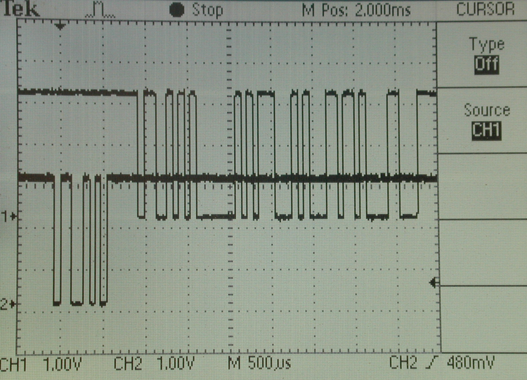
The bottom trace is sent from the controller to the sensor. The sensor response is shown in the upper trace. With the various modules available, for example these: https://www.digi.com/products/wireless-wired-embedded-solutions/zigbee-rf-modules/

How does one control the timing and recognition of the request data? Can anyone suggest a good introductory manual wth maybe some examples?

Thanks,

John
 

Attachments

  • oscope_level_150.png
    oscope_level_150.png
    692.2 KB · Views: 582
Last edited:
Several things to consider:
> This is command/response so both ends need to tx & rx. If command overlaps response (as trace image implies), you'll need 2 frequencies for full duplex communication. Otherwise, 1 frequency as half duplex will work.
> Either way you'll be way ahead using micros to manage it.
> You don't "Need" to break the protocol, just keep the pulse train exact. But, it's way easier if you do, they're probably using a std baud rate and format. I'd try asking the mfgr, they might surprise you.
> Going wireless, you may want some sort of block check / error detection scheme. Again, a micro is basically required to manage this.
Good Hunting, I've found RF to be a lot easier to say than do. <<<)))
 
Thanks for the response. I don't see any overlap in the request and response signals. They are about 350 uS apart. Request is the lower trace. I was hoping to find something like a "pass through" OOK transceiver. By pass through, I mean a transmitter that simply duplicates the on/off signal it gets. The receiver would just pass the signal through to the existing circuit (following inversion, if needed).

I was worried about the delays mentioned on the datasheets. As best I can tell in playing with the sender and display units on my bench, the response must be received within a certain window after the request. I don't believe the window is too tight, but some of the delays mentioned were in the 30 to 50 mS range, which might be a problem.

John
 
Just a quick update. As I thought about it, I realized I was making it more complicated than it needed to be. I just tried a pair of old LC series Linx Tx and Rx modules in the data line. It works (barely). I'll get something with a little faster data rate capability and see if that helps. It is also just on a solderless breadboard too.

Thanks for looking at the problem.

John
 
Last edited:
UPDATE

After a Summer of teaching ground hogs how to swim, I am back on this project.

Got a couple of xBee's this week and they look promising. Baud is 14,400. I used a PIC 12F509 to generate the query code (0)11001010(1) and the sensor sends nice data packets. The received and sent packets are almost identical. The control unit responds, but because the data to and queries from the control unit are out of sync, the linkage is not real stable. I am working on flow control at the control (receive) end and don't understand the RTS pin operation as described here:
Source: xBee manual
RTS Flow Control
If RTS flow control is enabled (D6 command), data in the serial transmit buffer will not be sent out the DOUT pin as long as RTS is de-asserted (set high). The host device should not de-assert RTS for long periods of time to avoid filling the serial transmit buffer. If an RF data packet is received, and the serial transmit buffer does not have enough space for all of the data bytes, the entire RF data packet will be discarded.

Specifically, what is meant by the "entire" RF packet. Does it mean just the newly arriving one or does it mean everything previously stored plus the newly arrived one? Can the size of the receive buffer be changed? How long after re-asserting RTS is the stored information released? Is there another way to store received data in the xBee and release on command?

Thanks,

John

BTW: I am concurrently working on storing the received data in another 12F509 and using that to sync with the control unit. But that looks like a little ( ;) ) more work.
 
Last edited:
RTS is "request to Send". it's also known as Hardware Flow. it's usually implemented as a circular buffer. it's a way to tell the Zigbee module to stop sending data because it can't process it for some reason.

Usually it will stop sending new data and you have to get the stuff out of the Zigbee buffer.

At least that would be my understanding.
 
When you give the XBee the data (0)11001010(1) it encodes it in a packet along with address, some sort of checksum, and other information. It takes several bytes to transmit a single bye. Now it is possible that the XBee could be sending more then one data byte per packet but in this peer to peer setup I am guessing not.

I have worked with similar radios and each packet is discarded by the RX unit after it has been read by the uC connected to the module. I do not recall but it would be nice if it was double buffered so you can act on the previous packet while the next one is arriving.

I am thinking you should be able to process the data on the display end fast enough so as not to need to use flow control.

Do you have a link where one can buy this specific type of level ?

Where are you with understanding the codes transmitted ?
 
Last edited:
Thanks for the replies. Here is a link to the level: **broken link removed**

As you might know, Sears puts all its tools on sale constantly. I paid about $24 for it last Spring. The actual sensor element is a Memsi MXD2020E/FL, Both the sensor board and controller board have microcontrollers on them. The sensor I believe is an 8051 (marked F301) -- not completely sure of either. I show what the data looks like in my earlier post. The display board is a COB glob.

The 12F509 directly interrogates the sensor (i.e., no RF link). That was done for development purposes. Once I get the control module timing solved, I can probably do away with that. I suspect the sensor simply sends raw PWM and temperature information in digital. The control module seems to do all of the calculations. I have not decoded the data, except to know that the first 8 bits are a repeat of the query and the last few bits look like noise.

I briefly thought of separating the LCD display and simply making that the remote. That is still a possibility, but I would probably end up having to buy a new LCD display, as the one on the unit would probably be destroyed in removing it to get at the data lines to it.

@KISS
There are two controls, CTS and RTS (plus RO) for hardware flow control. My understanding is that CTS operates on the transmitter side and the RTS on the receiver side. xBee sends a CTS to the MCU when it is ready for more data. That is not the issue here.

In this case, it is simply my grasp of the meaning/use of the RTS control on the receive end, Or, alternatively, whether the functionality I need is available at another pin. I had read many applications for xbees, but haven't studied them deeply. They seemed to be a pretty versatile units. That is why I bought them.

Remember, I have only had my pair since the weekend and have barely scratched the surface, like learning how to set them to 14,400 baud. They really are neat, but have significant latency because of the communication protocol overhead. So far, I have not been tempted to return to the Linx I tried in the Spring.

John
 
Last edited:
UPDATE2

Prompted by 3V0 (post#7), I wrote a little Assembly code to generate what is apparently a 7-byte data stream. (I can generate 8 bytes, if needed.) The first byte seems to be the handshake and repeats the query byte (0xCA). The second byte seems to be temperature: 0xF8 = 20°C and 0xF9 = 21°C. I am too tired to work on the other bytes tonight and have a busy day tomorrow. So, I won't be able to get to it until later. Anymore suggestions, help, etc? I still suspect the duty cycle is transmitted essentially raw without correction for temperature. Are there any common ways to transmit duty cycle?

John
 
Last edited:
Status
Not open for further replies.

Latest threads

New Articles From Microcontroller Tips

Back
Top