Continue to Site

Welcome to our site!

Electro Tech is an online community (with over 170,000 members) who enjoy talking about and building electronic circuits, projects and gadgets. To participate you need to register. Registration is free. Click here to register now.

  • Welcome to our site! Electro Tech is an online community (with over 170,000 members) who enjoy talking about and building electronic circuits, projects and gadgets. To participate you need to register. Registration is free. Click here to register now.
Status
Not open for further replies.

A_Wild_Noodle

New Member
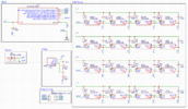
Hello all, this is one of my first electronic schematics and I'm trying to make sure everything looks good (electrically) before I order board and components. Another set of eyes on this to criticize and give constructive feedback would be great and point out any issues or mistakes my circuit may have! I think its easy enough to tell when this is, its a stand alone RGB LED array with its on little MCU. The purpose is to use an Arduino to use as a programmer for the on board ATTiny MCU so it can operate and loop through an animation where the only external connection is to power from a 5v DC supply. I think if anything the MISO MOSI lines are going to have to be revised. Attached are the datasheets for the LED's and the MCU as well as a screen shot of the schematic.
 

Attachments

  • RGB Array.PNG
    RGB Array.PNG
    124 KB · Views: 277
  • Atmel-2586-AVR-8-bit-Microcontroller-ATtiny25-ATtiny45-ATtiny85_Datasheet-Summary.pdf
    634.8 KB · Views: 258
  • RGB_LED_1811151230_Worldsemi-WS2812E_C139127.pdf
    741.8 KB · Views: 272
You need decoupling capacitors. The LED datasheet shows 100nF where you've got 22pF. Check the regulator datasheet for the capacitors required for that. And, what are the 56R resistors for?

Mike.
Edit, those LEDs can take up to 60mA each - that's 960mA - make sure your 5V supply is greater than 1A.
Also, not sure if the LM317 can work with a in to out voltage of 1.7V. You would be better off with a LDO linear fixed 3.3V regulator.
 
Last edited:
Pommie ah oversite regarding caps, the 56R's are for general current limiting to the LED's, figured it couldn't hurt and it may help keep the LED's cooler than if I was just to hook them up to 5V.
 
VDD and VSS are backwards.

Also the output voltage of the mcu run at 3.3v is not high enough to meet the input high requirement of the led. It must be 0.7xVDD=0.7x5v=3.5v, and the mcu will only put out 3.3v max
 
According to the datasheet, the WS2812B requires a minimum voltage of 6V but I've run them on 5V without problems. At least I think the supply was 5V.

Mike.
Edit, the WS2812E can run on 3.7V.
 
Last edited:
According to the datasheet, the WS2812B requires a minimum voltage of 6V but I've run them on 5V without problems. At least I think the supply was 5V.

Mike.
Edit, the WS2812E can run on 3.7V.
Where did you read 6V? If that was personal experience , you were over driving it to avoid the ringing and probably had interference from high inductive wires and not enough drive source damping R. add 50 ~120 Ohms is what I suggest for the low RdsOn CMOS drivers to 120 ohm twisted pair cable.

The WS2812B is not 6V but rather VDD +3.5~+5.3 V but 4.5 V min is recommended due to line drop. If using 3.3V then a level shifter or 5V buffer is needed.
 
Last edited:
I did a bit of digging on WorldSemi's site and found the attached PDF that seems to indicate that the WS2812E which is indicated in the OP's diagram is 3.3V MCU compatible with regard to the Din pin on a 5V supply to the LED - page 10

However, trying to find a proper 'E' version datasheet is a bit elusive.
 

Attachments

  • WS2812_Series_LED_Upgrade_Instructions(WORLDSEMI)-MINI-2018.11.28_18120810500261.pdf
    1.4 MB · Views: 244
I realized the E version could run on 3.7V - not 3.3V.
Edit, sorry, misread your post - 3.3V input compatible. But only on reduced voltage from 5V - 1 diode drop would suffice.
3.7.png

And the 6V came from the normal datasheet.
6V.png


Mike.
 
They are addressable LEDs Mike, all run off the one address line.
Not quite - the effective address is set by the physical position in the data chain.
Any with the DI in parallel or at the same pint in a parallel chain will display the same image.

The whole set needs to be in one long chain to have unique addresses within the chain.
 
According to the datasheet, the WS2812B requires a minimum voltage of 6V but I've run them on 5V without problems. At least I think the supply was 5V.

Mike.
Edit, the WS2812E can run on 3.7V.
I've always just run them off the 5V rail - I've always presumed the 6V suggestion was simply to remove the load from the 5V regulator, by powering them from the regulator feed.

As for the original circuit, how it is possible to get so many things so wrong on one simple circuit? - he even posted the datasheet which had been completely ignored, it might be in Chinese, but the diagrams are still clear.

Remove the unwanted resistors, replace the caps with 0.1uF, and wire the entire chain in series so they are addressable - plus add a level shifter, or use a 5V processor.
 
Status
Not open for further replies.

Latest threads

Back
Top