Continue to Site

Welcome to our site!

Electro Tech is an online community (with over 170,000 members) who enjoy talking about and building electronic circuits, projects and gadgets. To participate you need to register. Registration is free. Click here to register now.

  • Welcome to our site! Electro Tech is an online community (with over 170,000 members) who enjoy talking about and building electronic circuits, projects and gadgets. To participate you need to register. Registration is free. Click here to register now.

second order differential equations & Laplace

Status
Not open for further replies.
joy o joy, at last I have found the unit step response.
The problem was with the inverse laplace transform. Instead of the amplitude of the sine being 1, it depends on the damping factor = df/sqrt (1-(df*df)).
I would like to take the special case were R=0 i.e. the roots are complex. Your patience and assistance is always welcome.

Kind regards, Derek
 
Hi again,

I dont think you want R=0 because that means the capacitor is shorted out :)

Did you try using partial fraction expansion?
 
derrick007,

In post #5, you said,
Forcing input function is a square wave with zero offset and does not go negative

Well, if the square wave does not go negative, then it does indeed have a DC offset. If the square wave has an equal excursion above and below zero, and the positive value time is equal to the negative value time, then the Laplace of that square wave is 1/a(tanh(as/2), where "a" is the time at positive value or negative value. The square wave specified by you will be different because of its DC offset.

Ratch
 
derrick007,

In post #5, you said,


Well, if the square wave does not go negative, then it does indeed have a DC offset. If the square wave has an equal excursion above and below zero, and the positive value time is equal to the negative value time, then the Laplace of that square wave is 1/a(tanh(as/2), where "a" is the time at positive value or negative value. The square wave specified by you will be different because of its DC offset.

Ratch

Hello,


It appears that you made a mistake somewhere when calculating the Laplace Transform of a square wave that varies from -1 to +1 and has a period a.

First, there is no 's' in the denominator. Any function like this should have at least one 's' in the denominator.
Second, we rarely see the time period factor (or it's inverse) multiplying the function itself because the time period is almost never related to the actual amplitude for a square wave.
Third, if we take a=1 for the simplest case, then 1/tanh(s/2) is a staircase wave but only if we include the 's' in the denominator like so:
F(s)=1/(s*tanh(s/2))
Also, there's a missing close paren, but i assume it is at the end.

The transform you are looking for is not what he wanted, but yours is:
F(s)=tanh(a*s/2)/s
where you'll note the 's' in the denominator and we dont use the reciprocal of the tanh() function, and that's the square wave that various from -1 to +1 and has period 2a.

The function he wants is:
F(s)=1/(s*(1+e^(-a*s)))
where again the 's' appears in the denominator and again 2*a is the period of the square wave. That's the square wave that varies from 0 to +1. Including a scaling factor A, then it varies from 0 to A.
 
Last edited:
MrAl,

I apologize for not being more careful in transposing a mathematical expression into ASCII text. I did not calculate the expression. Look at the attachment for the correct expression. As you can see, and as I stated indirectly, the period is 2a.

Ratch
 

Attachments

  • 004.JPG
    004.JPG
    2 MB · Views: 383
Hello again,


That's better :)

Actually we didnt get that far yet anyway so i never checked his work on the square wave itself. He's still trying to get the step response first then go from there onto the square wave. I'll have to take a look back in this thread to find what he did with the square wave.

Looking back (post #6) it appears that he got the square wave part correct. He did a square wave with variable duty cycle rather than a 50 percent duty cycle square wave. That's a little more general too so i think he's ok with that part of the problem, so far.
 
Just a quick reply to the comments above - unfortunately over the past few weeks I have been unable to work on the transform, but I havent givent up. I am glad to see the interest it has generated.

As you know I have found the inverse transform for a unit step response - after some blood, sweat and tears !!!

Stay tooned for the next development - the plot thickens !!!
 
Hi MrAl

As you can see from previous threads, I eventually found the unit step response. I am now trying to find the periodic square wave response, as the attachments indicates.
My square wave has an amplitude of 23.5 with a period of 23.25 us. The duty cycle is 0.28, which means the "ON" time of the square wave (t1) is 6.5 us and the "OFF" time is 16.75 us.
Please find attached my derivation, which I have plotted on a spresdsheet (ss). The derivation tells me the output is periodic and should repeat every T seconds. Unfortunately my ss does not support this. I would expect to see the output rise upto t1 and then start to decay exponentially until T. This would be the first period, which would then repeated.

View attachment sqwave1.pdfView attachment sqwave2.pdfView attachment sqwave3.pdfView attachment sqwave4.pdfView attachment sqwavess.pdf

Again, your thoughts, comments and help would be very welcome.

Kind Regards, Derek
 
Hello again,


Ok very good, so just one question: did you test your results with a circuit simulator? That's the best way to verify your results. I could do it for you, but you'd learn more if you did it yourself. We can compare notes after that if you like :)
 
Hi MrAl
I have a basic analogue simulator - I need to purchase additional licenses to upgrade to allow me to carry out more advanced simulations.
I built the simple rlc circuit using the simulator and was able to carry out simulations upto 11Khz. I set the duty cycle at 28%, with an amplitude of 23.5 v and a frequency of 11 KHz.
The output was like a full wave rectified sine which looked like it would smooth out as a dc signal with small ripple if the frequency was increased to 43KHz. The sinewave amplitude varied between 5 and 10 v, which would smooth out to 7 or 8 volts. Not sure if my derivations and ss will provide the same results ? I have plugged in values in steps of 1 us upto 31 us and the output just continues to rise ? Not sure if this is correct as I expected the output to decay after t1 (=6us) and then start to rise again after T(=23us) ?
 
Hi,

Have you tried LT Spice? It's easy to use and free.

The output with a rectangular wave should damp out to a DC value with ripple if the frequency is high enough. If the input max is 10v then with 50 percent duty cycle you should see 5v at the output, with some ripple, and the ripple amplitude will be lower with increasing frequency.

We can use the 100uH, 22uf, and 10 ohms and with a 10v peak square wave input as the test set. I'll post my own results so you can compare.

Just to note, a ballpark ripple amplitude is:
Vpp=10*(5e9)/sqrt(121*w^4-1.075*10^11*w^2+2.5*10e19)


Here's the simulation using a 10v peak square wave 50 percent duty cycle, 10kHz, with the above values:
 

Attachments

  • LCR-001.gif
    LCR-001.gif
    14.9 KB · Views: 343
Last edited:
Hi MrAl
Thanks for getting back.

I have downloaded spicelt and have only started to use it. The problem I have is that I am not sure if my derivation of the time equation for the periodic square wave response is correct ? As can be seen from previous, my derivation concludes that if we let f(t) = step input response for a standard second order system, then the periodic square wave response = f(t) - f(t - t1), where t1 = width of the of the ON time = DT. D=duty cycle and T=period.
As I say, I am not sure if this is correct, because when I input this equation into a spreadsheet (ss) and start calculating output values from t=0 onwards, I dont get the response I am expecting, which is a dc voltage aprroximately 6v with a small amount of ripple. Therefore the question is, is my derivation correct or have I made a mistake when inputting the formula and/or values into the equation in the ss ?

Kind Regards, Derek
 
Hello again,


Well if you have a 60 percent duty cycle and a 10v peak square wave (that goes from 0 to 10v) then you should see a 6v average output with ripple as you are looking for. If you dont see that after a reasonable length of time, then something is still wrong.

I did look over your square wave transform and it looked good. So you combine that with your circuit transform to get the total response. For simulation however you have to also include the initial values of the energy storage components. Im not sure how you are calculating the response at this point, what method you are using.
 
I am pretty confident the square waveform transform is ok.

However, when I combine it with the circuit transform in order to find the output I am not so sure. For a periodic square wave response the output equation y(t) I get is y(t) = f(t) - f(t-t1), if f(t) is the unit step response ?
 
Hi,


Try writing out your solution in plain text here rather than in a pdf or bitmap file. It will be easier for me to read, thanks.
 
y(t) = B * [ y1(t) - y2(t) ], were B = amplitude of periodic square wave input = 23.5.

y1(t) = { 1 - e^-t/2RC * (A sinwt + coswt)}

y2(t) = { 1 - e^-(t-t1)/2RC * (A sinw(t-t1) + cosw(t-t1)} * { u(t-t1) }

t1 = Duty Cycle * Period, A = df/sqrt(1-(df*df)) : df = damping factor : w = (1/sqrt(L*C)) - (1/(2*R*C))
 
Last edited:
Hello again,


Well your transform should have factors in it that include parts that show the periodic nature of the result.

Lets digress slightly to a much simpler example that will illustrate the same thing...

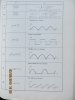
We start with a new circuit, with just a single resistor and capacitor, and RC low pass filter. This is made by connecting a resistor R to a capacitor C in series, with the other end of the cap to ground, and the voltage source connected to the other end of the resistor, and we take the output from across the cap. So we are looking at the voltage across the cap as our response. We first use a step wave input and then later we'll use a square wave input.

To start, we have the transfer function of the equation:
Vc(s)=Vpk/(s*R*C+1)

or more compactly:
Vc=Vpk/(s*R*C+1)

and now we will simplify this to use a peak voltage input of 1 volt and the RC time constant will be equal to 1 second, so we have:
Vc=1/(s+1)

The unit step time function is therefore:
Vc(t)=1-e^-t

or more compactly:
Vc=1-e^-t

Now you seem to be suggesting that we can replace the 't' in the above with 't-t1' where t1 is the duty cycle times the period, and use that as part of the solution. So doing that we get:

Vc2=1-e^-(t-t1)

and we already had Vc1:
Vc1=1-e^-t

So we subtract Vc1-Vc2 and get:
Vc=1-e^-t-(1-e^-(t-t1))


so we get:
Vc=e^(t1-t)-e^(-t)

Now say we have a 50 percent duty cycle and 1 second period, that means t1=0.5*1, so we have:
Vc=e^(0.5-t)-e^(-t)

as the final time result.

Now if we plot this we start with t=0, and there we get the solution:
Vc=0.64872127070013 volts

at t=0, and at t=5 we get:
Vc=0.0043710495391568 volts.

So we dont seem to get anything that is near 0.5 volts average.

Is this what you are trying to do, or did i miss something?

Note this circuit is much more simple so we can work with this much easier and faster for now just to illustrate the concepts.

Here is the simpler circuit:
Code:
Vin  o----R---+-------o  Vout
              |
              C
              |
GND  o--------+-------o  GND
 
Confused.

My original derivation for the rlc circuit included a delayed unit step as a multplier on the second term i.e. vc2.
Therefore I have used your equations above and changed the second term vc2, so that it includes a delayed unit step, u(t-t1). Unfortunately I have input this change into a ss and still do not get the correct answer, although it is a bit of an improvement as a t=0, Vc=0. However the output Vc reaches a maximum of 4 volts and then exponentially decays to zero.
I have tried several things like adding the output voltage Vc at the end of the first period to the start of the second period and to repeat this for each subsequent period, but to know avail. After t=5s the output voltage = 0.375v ??
 
Hi,

There are known ways to handle this for sure, but i wanted to see if you had another method that might work first. So i'd like to know where you got that method from, but i dont think it works. I was trying to illustrate with the RC circuit which i think we should turn to at least temporarily because it is much much simpler to deal with for experiments with the math.

Note that when i solve it the way you seem to be trying to do it, it doesnt give me very good results, but i was asking you to do that problem too so we can make sure we are both on the same page. With the RC circuit there are no sine and cosine terms so it's much faster, clearer, and easier to calculate all the necessary equations. Takes about five minutes.

So try that simple RC circuit and see what you come up with and we'll compare notes and go from there. Use the same method you were using for the RLC circuit.

ADDED LATER:
I think what you are trying to do is to add the delayed step function to the original function. But remember that the delayed step function is zero until the delay period starts. But also, doing this one single time does not result in a periodic waveform. It would have to be done for every period. Is this what you are trying to do?
 
Last edited:
Yes I think so.

I tried doing a derivation and came up with the following equation :

Vc(t) = (1 - e^-t) - { ( 1 - e^-t) * u(t-t1) } which is periodic and repeats every T (=1) secs ???? I tried inputting this into a ss with a few modifications based on my understanding of electronics and intial conditions etc. Assuming t1 = 0.5, then the output capacitor charges to 0.39 v after t=0.5 and holds this charge until t=T (=1sec) as the capacitor has nowhere to discharge to ? Therefore at t=T+, just after 1 sec. the capacitor starts to charge again to 1.5 secs where it reaches 0.78 v at which point it holds its charge again, until beginning to charge at t= 2T. The capacitor becomes fully charge at approximately t=2.3 secs, Vc(2.3) = 1v ?
 
Status
Not open for further replies.

Latest threads

New Articles From Microcontroller Tips

Back
Top