Continue to Site

Welcome to our site!

Electro Tech is an online community (with over 170,000 members) who enjoy talking about and building electronic circuits, projects and gadgets. To participate you need to register. Registration is free. Click here to register now.

  • Welcome to our site! Electro Tech is an online community (with over 170,000 members) who enjoy talking about and building electronic circuits, projects and gadgets. To participate you need to register. Registration is free. Click here to register now.

Sealed Lead Acid Battery Discharge Protection

Status
Not open for further replies.
I have now built the 6volt battery backup circuit.

The batt cut off part works fine but a few problem have come to light with the charging part of the circuit.

I set the batt float voltage to 6.75volts (no battery)but when a fully charged battery is connected the voltage drops to 6.5volts.

Also with no battery connected and the circuit in lock out there is 6.75 volts across the battery but when I press the reset button (to connect the load) the voltage drops to 6.25volts with no load connected.

I thought the regulator was supposed to keep the voltage constant?

I have checked the input 12v from my test supply and this does not drop at all.
 

Attachments

  • 6vbackup.jpg
    6vbackup.jpg
    85.8 KB · Views: 732
I have now built the 6volt battery backup circuit.

The batt cut off part works fine but a few problem have come to light with the charging part of the circuit.

I set the batt float voltage to 6.75volts (no battery)but when a fully charged battery is connected the voltage drops to 6.5volts.

Also with no battery connected and the circuit in lock out there is 6.75 volts across the battery but when I press the reset button (to connect the load) the voltage drops to 6.25volts with no load connected.

I thought the regulator was supposed to keep the voltage constant?

I have checked the input 12v from my test supply and this does not drop at all.

You are being fooled by the forward drop of the silicon diode. First, ignore the voltages with no battery in the circuit. The thing that matters is what the battery voltage settles to after 24 hours of continuous operation. For float charging an SLA, you should be at 2.25V per Cell, or 6.75V as measured right at the battery terminals. Each time you change the setting on the regulator, wait several hours to check the battery terminal voltage.
 
Hi MikeMl.
I see what you mean now. I adjusted the voltage at the battery terminations to 6.75volts presuming the volts drop at the diode would be taken into account. I did wonder why it only dropped 0.2 volts. So when I add more load to the circuit the diode drops it's full 0.6volts?

So I should add the battery in circuit and adjust the voltage to 6.75 volts and keep an eye on it and trim it down to maintain the 6.75 volts.

Thanks again for the info.

Brett.
 
have you ever considered a RTC chip for this purpose?

I see the clock is built from conventional logic.
it would be difficult to load the clock registers, and once you use a microcontroller, you don't need the explicit logic anymore.

but also do you really need a 6v lead battery to power the CMOS chips?

i made a CMOS LCD clock once, using the 4000 series, and overall current was 500uA.

it worked from 4x AA cells for 6 months.

it is NP to charge NiMH batteries with 1/20 or 1/30 current permanently, maybe capacity will drop over time, but they will not take damage.

by the way, good web page. there should be more such pages.
do you have a backup plan when GEOCITIES is closing later on this year?

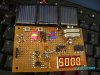
I show you one of my PIC clocks, powered by small solar cells, and 2.4 volts rechargeable battery.
it can work 24/7, the LED display is pulsed polyphase, 3 different pulsing schemes at once, and after a short moment, brightness is also dimmed.
works at 1mA average current!
it is hard to believe these small cells can power LED display 24/7 but it is true.

what I mean is, my suggestion is to pulse the display, in case power is lost, to reduce power consumption.
this could also be done with conventional CMOS logic.

maybe you do not want to use a smaller battery anyway.
 

Attachments

  • 3431445757_37499bcb2a.jpg
    3431445757_37499bcb2a.jpg
    124 KB · Views: 539
Hi MikeMl.
...
So I should add the battery in circuit and adjust the voltage to 6.75 volts and keep an eye on it and trim it down to maintain the 6.75 volts.
Yes, just connect everything as it will be with the clock running. Let it stabilize overnight. Monitor the battery voltage, and if an adjustment is needed, make it in small increments, waiting for several hours each time, allowing the battery to seek its own level. The goal is end up with the battery being at the correct float voltage.

Be advised that the ideal float voltage for your battery depends on ambient temperature. Look at your Battery Maker's web site. They usually have an application note that shows the float voltage expressed as V per Cell (VPC) and the temperature correction vs ambient temperature.
 
but also do you really need a 6v lead battery to power the CMOS chips?

The trouble is the clock has to power 5 one second slaves and 2 30 second movements along with an electromechanical chime. The 5 seconds slaves to not take much driving but the 30 second slaves and chime drive large electromagnets to lift the minute hand on a 12" clock dial and the metal hammer to strike a 4" bell.

If I had to build the clock again I would use PICs and would re-design the whole slave system.
The master clock itself like my knoledge is a bit retro and is completely hand wired because that was my trade back in the late 70s & 80s. I was a telephone exchange construction engineer so I build my projects to the same standards with all wires laced together with waxed twine not a cable tie in sight.

I am just getting into PICs now so who knows what I may build next. I can't see another Master Clock being build yet as this one works so well but you never know.

do you have a backup plan when GEOCITIES is closing later on this year?

I have many other web sites on various servers so I can move my sites if needed. I use BT Internet so as the Geocities is part of the package and not "free" so I presume I will be migrated onto a new server.

I have got to update my Master Clock site as it is getting a bit of a mess will all my mods, just got to find the time with all my other interests.
 
Be advised that the ideal float voltage for your battery depends on ambient temperature. Look at your Battery Maker's web site. They usually have an application note that shows the float voltage expressed as V per Cell (VPC) and the temperature correction vs ambient temperature.

I downloaded the pdf for my battery a while back which quotes 2.275 volts per cell or 6.825 volts. They show a very basic graph with charge and temperature but it is not realy possible to see the voltage / temp to any great accuracy. Voltage should decrease with temperature so I am presuming around 20 degrees C as the battery is indoors so have knocked it back to 6.75 volts.

This is where I wish my voltmeter was still calibrated.

Brett.
 
thanks for getting feedback, oliverb.

I know that not the ingredients are important but the effect that a circuit is producing, the control of matter that it can posess.

your design looks quite sophisticated and there are many options.
I did not understand also the mechanic clockwork is permanently updated.

clocks are also one my own fields of activity. recently, after two years searching the internet, I have become able to construct a transistor-based quartz crystal generator.
It is not strictly required in order to save cost, rather a specific design feature that I want to have for some reason.

I have...maybe 5 or 6 clock prototypes, some taken apart again, and some new PCBs yet not completed. all based on PIC (microcontroller).
it might be 7 or 8 circuits altogether.
 
Lol

LOL Not at all.
Brett.

Well I have to ask finally. Litle kids used to use this and I always read it as Little old love .
Is that what it means and do you realy want to say that to a bloke in your posts?

Little old lady , locked out lately ,lick our lips ........its got me confused
 
It stands for Laugh Out Loud. I think it could be UK SMS or Messenger shorthand. I have used it for so long I forget where it came from.

Sorry for the confusion.
 
Project update

A quick update on this project.
I ran this circuit on one of my old clocks without a hitch. I turned off the power and the clock ran off my battery with no problem. I connected an old torch in the circuit to flatten the battery a bit quicker and the circuit shut down at the correct voltage only comming back to life when th reset was pressed. The battery started charging again as soon as the power was restored.

The problem I have is my master needs slightly more voltage to run than the 6 volt backup battery can deliver. I think this is due to the logic feeds that reset the count on 60sec etc
being taken off the display. Running off this circuit the counts do not reset and just keep going upto 99.

When I designed the clock my circuit simulator showed it would not work but I built each stage on breadboard and it worked fine in real life.

I'm not going to change my clock now as I don't want to take it apart again. Anyway I have a use for the 6 volt battery backup on my weather server so the effort will not go to waste.

While my clock was down this morning I measured the current and it peaked around 200mA (5watts power consuption from the 240v socket) without driving the electromechanical chime. I'll prob move the chime off the clock power onto the seperate 30sec slave supply to keep all the power hungry and noisy stuff together.

Thanks MikeMl etc for you help in getting this project working.
 
Status
Not open for further replies.

Latest threads

New Articles From Microcontroller Tips

Back
Top