Continue to Site

Welcome to our site!

Electro Tech is an online community (with over 170,000 members) who enjoy talking about and building electronic circuits, projects and gadgets. To participate you need to register. Registration is free. Click here to register now.

  • Welcome to our site! Electro Tech is an online community (with over 170,000 members) who enjoy talking about and building electronic circuits, projects and gadgets. To participate you need to register. Registration is free. Click here to register now.

Sealed Lead Acid Battery Discharge Protection

Status
Not open for further replies.

oliverb

Member
I want to build battery backup for my Master Clock so it keeps running when mains fails.
My Master Clock page is here.
**broken link removed**

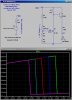
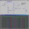
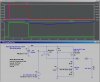
I have the basic charging and backup circit (see diagram) using a 6v sealed lead acid battery.

The circuit works fine but my only concern is that a long power cut will discharge my battery too far and shorten it's life.

Is there a circuit for discharge protection so I can preset a voltage where my battery is taken out of circuit?

I notice solar panel regulators have this function built in but they all work with 12v batteries.

Thanks.
Brett.
 

Attachments

  • batt backup.jpg
    batt backup.jpg
    101.8 KB · Views: 4,318
Here is something I posted for just a visual LED indication that a 12V SLA has discharged too low. You can use this basic circuit by tailoring the voltage divider on the Ref input to the TL431, and modifying the output side to switch off your load. Can you do that, or do you want some help?
 

Attachments

  • LowVoltageLED.jpg
    LowVoltageLED.jpg
    176.1 KB · Views: 2,739
Here, I modified it for you: Scale the time axis to match the discharge time of your battery. What do you want to use as the final cutoff voltage? If I didn't guess it, you can play with the resistive divider. I'm taking a wag that the 2n3906 will drive your clock. If not, you could use a bigger PNP or a PFET.
 

Attachments

  • 6VCutOff.jpg
    6VCutOff.jpg
    167.1 KB · Views: 2,543
Last edited:
Thanks MikeMl.

I did measure the current from the PSU of my clock and I think it was 300mA ( I should have written it down). There is also another 250 to 350mA to drive the electro mechanical chime on the hour. This is max 12 x 350mA pulses on the hour into an electromagnet.

The 30 second electromechanical slaves are powered from a seperate supply so I will sort the supply for this later.

In your circuit if the battery was disconnected when it dropped below a set voltage would it try to switch back on when the battery voltage raised again due to no load?

If so I could use the OP transistor to switch off a relay instead of the battery. I could then configure the relay to hold itself off via it's own contacts. Therefore once the voltage threshold had been reached the relay releases shuting down the power to my clock and holding itself off.

A reset button would have to be pressed to reset the relay.
 
Hi Eric
The battery is floated at 6.75 volts.

Brett.

hi,
Im sure that Mike will modify his circuit so that it has hysteresis from 5.4V to 6.6V.
In that way the auto low cut off will reset to ON when the mains is restored.

OK.:)
 
The circuit as presented the last time already exhibits some hysteresis, as defined by the 2.2meg feed-back resistor. It creates a nice clean switching threshold, and the circuit will not cut back in until the battery voltage is about 200mV higher than where it cut out.

The attached circuit as modified to increase its load switching capacity by replacing the PNP with a PFET. It will now switch an Amp or three. I also modified it so that it includes the explicit push button to restart it. Note that I lowered the estimated load being switched to 20Ω.
 

Attachments

  • 6VCutOff.jpg
    6VCutOff.jpg
    203.5 KB · Views: 1,478
Last edited:
hi Mike,
My experience with SLA batteries shows that the battery will 'recover' to a voltage much higher voltage than 200mV, as soon as the load comes off.

I would predict the circuit will tend to repeatedly switch on/off, at the battery low point.
 
...
I would predict the circuit will tend to repeatedly switch on/off, at the battery low point.

Good Point! Either modify the circuit to increase the hysteresis or use the version with the push button, which will not start again unless the button is pushed.
 
Last edited:
Thanks you so much for your help on this. The push button idea is great! I will give it a try on breadboard as soon as poss and let you all know how I get on.

Brett.
 
Quick question. The TDL431 is stocked with many codes after the 431. Can you tell me what type in your circuit so I can get the data sheet?

Thanks.
Brett.
 
**broken link removed**you go. I find these little buggers about as useful as 555s, so I bought 20 from Mouser in the TO-92? plastic transistor package.
 
Last edited:
Umm maybe I'm missing something but isn't the point of battery backup to NOT let the clock fail?? Can't you just run a bigger battery?

For my master clock I have a 12v 45 amp-hour car battery, kept on float charge at 13.8 volts, then the entire system is run from the 12v battery. When we get the (typical) 4 hour blackouts the battery barely dips. My battery is a little sulphated, but it easily supplies 1 amp for 12 hours, and my system is only 100mA or so for master clock and peripherals.

If you separate the actual clock from the peripherals with diodes, (bacause you don't need chimes and line drivers etc in a blackout), using the battery to preserve just the clock counter. You might be able to get your 300mA down to 50mA. :)

The way i see it, designing the failsafe system to deliberately shut off is a real poor solution. It's like designing a parachute so that if you are a bit heavy on that day the 'chute breaks away so it doesn't get damaged. ;)

(edit)After looking at your clock schematic, it seems you use the 7-seg display drivers as part of the clock itself, so you can't power them down to conserve energy, BUT you could drive the common cathode of all the displays with a transistor to ground, and operate the transistor base from the 7.35v junction in your backup supply. That way the displays will power down in a blackout but the clock count itself will be maintained, and current should be down to a handful of mA.
 
Last edited:
We get around 4 or 5 power cuts each year probably around 10 if you include the small 1 second shutdowns. The power seems to be out for around 4 hours each time. I have also shut down the power myself many times while renovating the house but only for around 30mins or so.

I have chosen a 12ah battery as it should cope with 99% my power fails at minimal cost. Don't forget the max life is around 5 years if just kept on float charge so if I buy a larger battery that will probably never be used I am not getting a good return for my money.
 
So you have a 12 ah battery, derate it to maybe 8-10 ah since float charge won't be "full charge" so to speak. That's still good for a LOT of hours if your clock takes 300mA.

No thoughts on adding a transistor or some diodes to reduce the blackout consumption, rather than spend that effort on a battery saver? It just seems better to maximise the "functioning" safety of the system rather than add a level of extra protection that (if it ever is used) kills the safety ie kills the clock data.
 
No thoughts on adding a transistor or some diodes to reduce the blackout consumption, rather than spend that effort on a battery saver?

If I was to build the clock again I would do-but then if there was a really long power cut I would still loose the clock data and also a battery.

I am prepaired to have to reset my clock every 10 to 15 years if there is a very long power cut. I will probably have moved by then so will have to power it down anyway.
 
Status
Not open for further replies.

Latest threads

New Articles From Microcontroller Tips

Back
Top