#include <p18f4620.h>
#include <delays.h>
#pragma config OSC = INTIO67, WDT = OFF, LVP = OFF
typedef unsigned long LBA;
void set_wren(void);
int initMedia(void);
int sendSDCmd(unsigned char,LBA);
void delay_s(unsigned char);
void delay_ms(unsigned char);
void delay_us(unsigned char);
unsigned char writeSPI(unsigned char);
int writeSector(LBA a,char *,char *);
int readSector(LBA a, char *, char *);
unsigned char var;
#pragma udata data1
char data1[256];
#pragma udata data2
char data2[256];
#pragma udata buffer1
char buffer1[256];
#pragma udata buffer2
char buffer2[256];
#define CSel LATDbits.LATD2
#define LED LATDbits.LATD1
void main(void)
{
LBA addr;
int i,r;
TRISC=0b00010000;
TRISD = 0;
CSel=1; //init chip select (active low)
LED=0; //LED off
SSPSTAT = 0b00000000; //SMP(7)=0, CKE(6)=0 (clock edge idle to active), others don't care
SSPCON1 = 0b00010010; //CKP(4)=1 clock polarity (idle high)
//SSPM3:SSPM0(3:0)=010 spi clock FOSC/64 (<400kHz)
SSPCON1bits.SSPEN=1; //SSPEN(5)=1 enable SPI
for(i=0;i<256;i++){ //fill the buffers
data1[i]=i;
data2[i]=i;
buffer1[i]=0; //and clear the receive buffers
buffer2[i]=0;
}
r=initMedia();
[COLOR="Red"] if(r){ //card init failed - 1 blink
[/COLOR] while(1){
LED=1;
delay_ms(200);
LED=0;
delay_s(1);
}
}
else{ //write card
addr = 10000;
for(i=0;i<1000;i++){
if(!writeSector(addr+i,data1,data2)){
while(1){ //write failed - 2 blinks
LED=1;
delay_ms(200);
LED=0;
delay_ms(200);
LED=1;
delay_ms(200);
LED=0;
delay_s(1);
}
}
}
addr=10000; //verify write
for(i=0;i<1000;i++){
if(!readSector(addr+i,buffer1,buffer2)){
while(1){ //verify failed - 3 blinks
LED=1;
delay_ms(200);
LED=0;
delay_ms(200);
LED=1;
delay_ms(200);
LED=0;
delay_ms(200);
LED=1;
delay_ms(200);
LED=0;
delay_s(1);
}
}
if(memcmp(data1,buffer1,256)||memcmp(data2,buffer2,256)){ //verify
while(1){ //mismatch - 4 blinks
LED=1;
delay_ms(150);
LED=0;
delay_ms(150);
LED=1;
delay_ms(150);
LED=0;
delay_ms(150);
LED=1;
delay_ms(150);
LED=0;
delay_ms(150);
LED=1;
delay_ms(150);
LED=0;
delay_s(1);
}
}
}
}
while(1){ //success!
LED=1;
delay_s(1);
LED=0;
delay_s(1);
}
}
int writeSector(LBA a,char *p1,char *p2)
{
unsigned r,i;
LED=1; //turn on write LED
r=sendSDCmd(24,(a<<9));
if(r==0){
writeSPI(0xfe); //send Data Start byte
for(i=0;i<256;i++) //first 256 bytes
writeSPI(*p1++);
for(i=0;i<256;i++) //second 256 bytes
writeSPI(*p2++);
writeSPI(0xff); //send dummy CRC
writeSPI(0xff);
if((r=writeSPI(0xff) & 0x0f) == 0x05){ //check if data accepted
for(i=10000;i>0;i--){
if(r=writeSPI(0xff))
break;
}
}
else
r=0; //fail
}
CSel=1;writeSPI(0xff); //disable SD
LED = 0; //LED off
return(r);
}
int readSector(LBA a, char *p1, char *p2)
{
int r,i;
LED = 1; //turn on read LED
r = sendSDCmd(17,(a<<9));
if(r==0){ //check if command was accepted
i=10000; //wait for a response
do{
r = writeSPI(0xff);
if(r==0xfe)
break;
}while(--i > 0);
if(i){ //if no timeout, read 512 byte sector
for(i=0;i<256;i++)
*p1++ = writeSPI(0xff);
for(i=0;i<256;i++)
*p2++ = writeSPI(0xff);
writeSPI(0xff); //ignore CRC
writeSPI(0xff);
}
}
CSel=1;writeSPI(0xff); //disable SD
LED = 0; //read LED off
return(r == 0xfe);
}
int initMedia(void)
{
int i,r;
CSel=1; //while card is not selected
for(i=0;i<16;i++) //send 80 clock cycles to start up
writeSPI(0xff);
CSel=0; //then select the card
r = sendSDCmd(0,0); //send reset command to enter SPI mode
CSel=1;writeSPI(0xff); //disable SD
if(r != 1) //error check - need 1
return 0x84;
i = 10000; //send init for up to 0.3s
CSel=0;
do{
r = sendSDCmd(1,0); //send init command
CSel=1;writeSPI(0xff); //disable SD
if(!r) break;
}while(--i > 0);
if(i==0) //time out error 0x85
return 0x85;
SSPCON1 = 0x30;
return 0;
}
int sendSDCmd(unsigned char c, LBA a)
{
int i,r;
CSel=0; //send command packet (6 bytes)
writeSPI(c|0x40); //send command & frame bit
writeSPI(a>>24); //send 32-bit address
writeSPI(a>>16);
writeSPI(a>>8);
writeSPI(a);
writeSPI(0x95);
i=9; //wait for response
do{
r=writeSPI(0xff); //check if ready
if(r != 0xff)
break;
}while(--i > 0);
return(r);
}
unsigned char writeSPI(unsigned char send)
{
SSPBUF=send;
while(!SSPSTATbits.BF);
return SSPBUF;
}
void delay_s(unsigned char x)
{
char var1;
for(var1=0;var1<x;var1++)
{
Delay10KTCYx(200);
}
}
void delay_ms(unsigned char x)
{
char var1;
for(var1=0;var1<x;var1++)
{
Delay1KTCYx(2);
}
}
void delay_us(unsigned char x)
{
char var1;
for(var1=0;var1<x;var1++)
{
//Delay10TCYx(2);
Delay1TCY();
Delay1TCY();
}
}

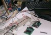


 kinda beat up but heh free for now lol ill buy it when i get paid