Continue to Site

Welcome to our site!

Electro Tech is an online community (with over 170,000 members) who enjoy talking about and building electronic circuits, projects and gadgets. To participate you need to register. Registration is free. Click here to register now.

  • Welcome to our site! Electro Tech is an online community (with over 170,000 members) who enjoy talking about and building electronic circuits, projects and gadgets. To participate you need to register. Registration is free. Click here to register now.

Schmitt trigger simulation

Status
Not open for further replies.
hi Al,
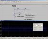
Interestingly is the difference between the observed frequency from the LTS plot of ~141kHz and the ~76kHz from your formula, which is more accurate than the 83kHz derived from the 1/[1.2*RC].

To get a 141kHz from your formula I had to set the vL=1.9v vH=3.5v and Vss=4.8v
[of course there other combinations that give the 141kHz]

Its appears that LTS is using different vL, vH and Vss from its plotted values of Vc.????

Strange.

Hi there Eric and Irjaj,

Eric:

Thanks for looking at this. I checked the formula but i didnt do like 100 problems with it yet :)

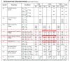
Anyway, from your previous post i can see that the model you are using has characteristics such that vL=2.1 and vH=2.9. This of course means we need to plug those two values into the formula to get it to work correctly. I took the time to derive the formula using vL and vH so that people that wanted to use this kind of oscillator could investigate the oscillator properties with variations in either vL or vH or both, either randomly or systematically.
If we do plug in those two values and use Vcc=4.8 instead of 5.0, with a 10k resistor and 1nf capacitor we come out with a calculation of 148330Hz, which is pretty close to the observed frequency using LT Spice according to your simulation. We could investigate and tweek the formula a bit i guess.

I would suggest that anyone trying to use this oscillator to simply ignore the formula 1/(1.2*R*C). I think that formula is a spinoff of an oscillator with thresholds of 1/3 Vcc and 2/3 Vcc, which comes out to a neat 1/(1.386*R*C) (and as a side note this can be derived from the formula i gave previously). In other words, we have no guarantee that we'll see 1/3 and 2/3 Vcc thresholds so we cant rely on that simpler formula. As we can see by comparison the simple formula fails completely in many cases.

Irjaj:
The derivation of that formula is not especially difficult, just takes some attention to what is going on with an oscillator like this kind.
The first thing to notice is that the oscillator only has two output states: either the output is high or the output is low. Knowing this, and knowing how the capacitor charges and discharges through a resistor gives us enough to go on. We are working with two different time periods, the charge time and discharge time, so it's convenient to figure out the two time periods and then add them together to get the total time period tp, then take the inverse because F=1/tp.

Starting with the output low, we can note that just before it went low the cap was charged to vH. This means we can use the formula for the discharge period we'll call t1:
vH*e^(-t1/RC)
and since the cap is discharging from vH to vL we can set that equal to vL and we get:
vL=vH*e^(-t1/RC)

Now when the output goes high, we can use the formula for a cap charging through a resistor powered from a voltage source where the voltage source is the output high voltage Vcc (t2 is the charge period):
(Vcc-vL)*(1-e^(-t2/RC))+vL
and because the cap charges from vL to vH we set that equal to vH:
vH=(Vcc-vL)*(1-e^(-t2/RC))+vL

Now we have two equations and two time periods t1 and t2:
vL=vH*e^(-t1/RC)
vH=(Vcc-vL)*(1-e^(-t2/RC))+vL

Now all we have to do is solve each equation for its respective time period (t1 or t2) and then add the two results together. After simplifying a little, the result is the formula i gave previously:
tp=t1+t2=RC*(ln((vL-Vcc)/(vH-Vcc))+ln(vH/vL))

and as i noted we throw in a little fudge factor making the supply voltage Vcc equal to 4.8v instead of 5v to get a little better correlation with real world results.
 
Last edited:
hi Al,
Checking thru d/s for the CD40106 it can be seen that the spread in the vH, vH and hysteresis is large.

I have found in the past that trying to use a fixed value resistor, expecting to find the calculated frequency is not going to happen.:)

A fixed and variable resistor is required to get close to the desired frequency.

I Set the LTS model as shown in this image.
BTW the vH = is the sum of the two entered values and vL is the difference.

Frequency is lower than expected, but within the parameters spread.
 

Attachments

  • AAesp08.png
    AAesp08.png
    89.8 KB · Views: 361
  • AAesp09.gif
    AAesp09.gif
    52.4 KB · Views: 379
Last edited:
can you plaese tell me how you get the lower threshold to 1.2 -.4 = .8V, and the upper threshold to 1.2 + .4 = 1.6V
Look at the LTSpice Help for the Digital components. Vt sets a threshold value and Vh sets a hysteresis value. The Schmitt upper threshold = Vt+Vh and the lower threshold = Vt-Vh.
 
Hi,
I write a report and need a formula for it? f = 1 / (k.R.C) and K = ln [(VH / VL). (Vcc-Vl/Vcc-VH)] but it doesnt work!! :(
 
hi Al,
Checking thru d/s for the CD40106 it can be seen that the spread in the vH, vH and hysteresis is large.

I have found in the past that trying to use a fixed value resistor, expecting to find the calculated frequency is not going to happen.:)

A fixed and variable resistor is required to get close to the desired frequency.

I Set the LTS model as shown in this image.
BTW the vH = is the sum of the two entered values and vL is the difference.

Frequency is lower than expected, but within the parameters spread.

Hi Eric,

Yes, the threshold point spread is pretty large and that is what i have been trying to get across. By posting the formula, i had hoped that people would use it to calculate their frequency spread based on the data sheet spread. That is, we can look at the data sheet and do a few calculations and then know that if we buy a one piece order of that chip we might get a frequency F1, but if we buy a two piece order we might get frequency F1 from one chip and frequency F2 from another chip. We cant nail it down perfectly, but doing this kind of calculation will show us how much variation we might expect from these chips in this kind of circuit.

I'll have to see if i can get a chance to play around with that LT spice model.
 
Hi,
I write a report and need a formula for it? f = 1 / (k.R.C) and K = ln [(VH / VL). (Vcc-Vl/Vcc-VH)] but it doesnt work!! :(

Hi,

I have no idea what you mean by that. Maybe you can be more specific what it is you are trying to do and why you cant do it. You'll need to be more specific and clear so we can understand what you want.
 
You didn't use the formula accurately (brackets missing).
Try K = ln [(VH / VL). (Vcc-VL)/(Vcc-VH)]
 
hi eric,
can you please tell me, what can i do to get this??

hi,
It is just to show the frequency of the plot when using the LTS Schmitt model with those threshold values.

Have you tried recalculate the frequency using Al's formula.???
 
Hi,
i can t see the frequenz in LTspice like you??

Hi,
You have to select '2 cursors' #1 and #2,,,, move #1 cursor to the peak of the wave and the #2 cursor to the next peak.
 

Attachments

  • AAesp10.gif
    AAesp10.gif
    7 KB · Views: 332
Hi again guys,


Since the output of the Schmitt Trigger chip may not go exactly to zero volts when the output state is low, i have decided to rework the equation for the frequency to include the output saturation voltage. This makes the formula a little more accurate than before:

t1=RC*ln((Vcc-vL)/(Vcc-vH))
t2=RC*ln((vH-vSat)/(vL-vSat))
tp=t1+t2
F=1/tp

where
Vcc is the supply voltage minus the output sat when the output is high,
vSat is the output saturation voltage when the output is low,
t1 is the charge time low to high,
t2 is the discharge time high to low,
tp is the total period,
F is the frequency.

I tried this with a 74HC14 ic chip simulation and 10k and 0.1uf and vSat=0.176v and Vcc=4.8v and got a result calculation of 1116Hz (plus or minus some small measurement error) and with the new formula for F i calculated a frequency of 1118Hz. That's less than 1 percent difference (actually about 0.2 percent which is two tenths of one percent). That's close enough for me. The error will however go up for higher frequencies where the calculated frequency comes out higher than the actual real life frequency because of the internal effects of the chip itself that begin to play a more important role as their time values come closer to the charge and discharge times.

If we wanted to we could repeat the derivation to include output rise and fall times, but i really dont think this is necessary when all we want to be able to do really is study how the input thresholds affect the output frequency.

I've got a challenge for anyone who feels up to it: using one or more of these chips and any passive devices (resistors, capacitors, diodes) build a 50 percent duty cycle oscillator

I've got another challenge for anyone who feels up to it: using one or more of these chips build a 50 percent duty cycle oscillator WITHOUT using diodes. Maybe we should include the NAND Schmitt Trigger chip type here too.
Is it even possible without using diodes? We will find out :)
 
Last edited:
I've tried just derive your formula, unfortunately I get incorrect results
VL = ^ VH.e (-t1/RC)
VL / VH = e ^ (-t1/RC)
ln (VL / VH) =- t1/RC
t1 =- RC.ln (VL / VH)
t1 = RC.ln (VH / VL)
t2 =- RCln [(VH-VL) / (Vcc-VL) -1] is very wrong
Can you please tell me where I can find the correct derivation
thank you
 
Hi,

For the charge time with cap charging low to high we have:
VH=(Vcc-VL)*(1-e^(-t/RC))+VL

Solve that for t and you'll get your answer.

For the charge time with cap discharge high to low we have:
VL=VH*e^(-t/RC)

Solve that for t and you'll get the other charge time.

Note however that i had included the output saturation voltage vSat into the new formula i posted in the post just before your last post (#33)...

t1=RC*ln((Vcc-vL)/(Vcc-vH))
t2=RC*ln((vH-vSat)/(vL-vSat))
tp=t1+t2
F=1/tp

t1 is cap charge time, t2 is cap discharge time.
 
Last edited:
Starting with:
VH=VL+(1-e^(-t/RC))*(Vcc-VL)

subtract VL from both sides and we get:
VH-VL=(1-e^(-t/RC))*(Vcc-VL)

divide both sides by (Vcc-VL) and we get:
(VH-VL)/(Vcc-VL)=1-e^(-t/RC)

subtract 1 from both sides and we get:
(VH-VL)/(Vcc-VL)-1=-e^(-t/RC)

multiply both sides by -1 and we get:
1-(VH-VL)/(Vcc-VL)=e^(-t/RC)

take the natural log of both sides and we get:
ln(1-(VH-VL)/(Vcc-VL))=-t/RC

multiply both sides by -RC and we get:
-RC*ln(1-(VH-VL)/(Vcc-VL))=t

therefore we get:
t=-RC*ln(1-(VH-VL)/(Vcc-VL))

and if we simplify the inside part of the ln() which is
1-(VH-VL)/(Vcc-VL)

we find that can be expressed as:
(VH-Vcc)/(VL-Vcc)

so as result we get:
t=-RC*ln((VH-Vcc)/(VL-Vcc))

and now if we invert the inside of the ln() function we can eliminate the minus sign, so we get as final result:
t=RC*ln((VL-Vcc)/(VH-Vcc))

Of course there are some constraints on VL and VH in relation to Vcc, but in normal usage for this application this wont be a problem.
 
Last edited:
Hi again,

Are you familiar with Laplace Transforms, or have you worked with the slightly simpler form for a charging capacitor:
Vc=E*(1-e^(-t/RC))
where E is the source voltage ?

We can start from scratch or from 1-e^(-t/RC) which is simpler.
 
Last edited:
Hi again,

Maybe i should have asked what kind of analysis have you done in the past? We can start from what you already know about circuit analysis, unless you're very rusty or something then we'll just jump in and see what you can pick up out of it.
 
Status
Not open for further replies.

Latest threads

New Articles From Microcontroller Tips

Back
Top