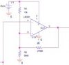
hi could someone please tell me how to make my upper trigger point 2.8V and my lower trigger point 1V
what resistor values do i choose to make that happen. Say the resistor connected to ground is 10K
i realize the current schematic won't make much sense to most, but i can't feedback my trigger output to the mosfet gate just yet. at least not without a switch to vary the voltage at the trigger input.
Do you really need a +12 -15V swing on your comparator?
Do you realize the LM339 has low drive current on high side which affects Vmax drop from Vcc?
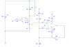
Your feedback R is far too low a value and loads the Vmax. switch to a LM339 comparator with open collector maybe for logic levels OR JUST vGS LEVELS
edit
I just realized why your design wont work.
A comparator Schmitt trigger cannot use positive feedback AND Pullup/down resistors to choose bias and hysteresis with an INVERTING input.
Hysteresis must be independently controlled for Mean threshold and +/- peak threshold around mean and choosing pull down resistor changes hyst. AND mean threshold at the same time.
So you can use a programmable zener to set mean voltage or use Vref on Vin(-) and use non-inverting mode of comparator. e.g. in your case. Vmean =1.9V and Peak swing is 0.9V.
If using a single supply comparator with 0-20V swing 0.9V peak swing ( 1.8Vpp) means the feedback ratio is 20/0.9 =22.
If you use +/-15V swing, can it drive the current for Ciss on Vgs on fast transitions?
Do you want fast shutoff and slow turnon?
This means you
cannot use the inverting input in this case to set HYST and Vmean independently with R ratios only. The Vref must be a low impedance source.
Although I dont know what the end result is... A hickup PWM current regulator? CC sink?