Continue to Site

Welcome to our site!

Electro Tech is an online community (with over 170,000 members) who enjoy talking about and building electronic circuits, projects and gadgets. To participate you need to register. Registration is free. Click here to register now.

  • Welcome to our site! Electro Tech is an online community (with over 170,000 members) who enjoy talking about and building electronic circuits, projects and gadgets. To participate you need to register. Registration is free. Click here to register now.

Schematic Reading Help

Status
Not open for further replies.
Hi DMW,
The hFE of a transistor is used only when it is a linear amplifier and it has plenty of collector to emitter voltage. A transistor need much more base current for it to be a saturated switch. Its max saturation voltage is listed in its datasheet with its base current 1.1oth the collector current no matter how high is its hFE.

Your math does not make sense.
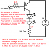
The IR LEDs have a voltage drop of about 1.3V each and the saturation voltage of the transistor is 0.1V. So the 200 ohm current-limiting resistor has 6.3V across it and therefore its current and the current in the LEDs is only 31.5mA.
 

Attachments

  • transistor LED driver.PNG
    transistor LED driver.PNG
    23.2 KB · Views: 491
Hi

Thanks for the information, to clarify, my emitter > base current has to be at least 1/10th of the emitter > collector.
Where did you find that in the datasheet? The only two things I can tell are:
Vce(sat) : Ic = 100mA / Ib = 5mA
Vbe(sat) : Ic = 100mA / Ib = 5mA

and 100/5 = 1/20th?

Also I didn't know off my head what current an IR-LED needed so I guessed :).
 
You probably looked at the datasheet of a BC558 that shows a poor saturation voltage of 0.9V max when its collector current is 100mA and its base current is 5mA. it would saturate with a lower voltage drop if its base current is 10mA.
 
It would be better to tie the LEDs to Vcc instead of ground because of the duty cycle output by the 555. This will use less power but give the same peak output:
 

Attachments

  • remote jammer.PNG
    remote jammer.PNG
    32.5 KB · Views: 206
Last edited:
It would be better to tie the LEDs to Vcc instead of ground because of the duty cycle output by the 555. This will use less power but give the same peak output:

You have to produce 38kHz to jam the TV remote. That being said, does it really save power connecting the LED to Vcc instead of ground?

I understand what you mean about duty cycle but if the signal has to be 38kHz, isn't the duty cycle the same no matter which way you connect it?
 
The timing capacitor in your 555 circuit charges slowly through 3 resistors in series but discharges through only the 1k resistor. So the output is high for a long time and is low for a short time.

The peak current in the IR LEDs is about 32mA but a remote uses a peak current of about 100mA so the range of this jammer will not be far.
 
You have to produce 38kHz to jam the TV remote.

Why?

I would bet 20KHz also works.

If there is a single pulse out of place or an extra pulse in the IR data stream, the IR decoding will fail to decode it as a valid command.
 
The frequency of the IR jammer probably does not matter much. A DC IR light will blind the IR receiver but will have double or more the current of a pulsed one.
 
What type of IR LED's do remotes have that they can withstand 100mA?

Also, from my experimenting with this circuit, on my TV the frequency did matter. I do not know exactly what the frequency is (although I have read that it is 38kHz) because I just turned the potentiometer until the remote could no longer raise the volume. I am currently working on a newer, more efficient schematic that will hopefully work just as well and at longer ranges.
 
In order for a remote to work 10m away and with it pointed in the wrong direction, it hammers the IR LEDs with pulses of about 100mA. The pulses are very short duration so the average current is less than the 30mA max allowed continuous rating for the LEDs.
 
In order for a remote to work 10m away and with it pointed in the wrong direction, it hammers the IR LEDs with pulses of about 100mA. The pulses are very short duration so the average current is less than the 30mA max allowed continuous rating for the LEDs.

So then at what frequency do TV remotes transmit or does each button press transmit at a different frequency? If there is no specific frequency needed then can I just connect the IR LED to Vcc instead of ground and set the 555 to a very small duty cycle?
 
TV remotes have a carrier frequency of about 36kHz, 38kHz and a few other frequencies. The carrier is digitally modulated, each button has its own digital code.
I think a jammer will work at one-half and one-third of the carrier frequency as well as at the carrier frequency.

A 555 has a max allowed output current of 200mA when its supply voltage is higher than 5V so a transistor is not needed to drive the IR LEDs.
 
TV remotes have a carrier frequency of about 36kHz, 38kHz and a few other frequencies. The carrier is digitally modulated, each button has its own digital code.
I think a jammer will work at one-half and one-third of the carrier frequency as well as at the carrier frequency.

Why do you think it will work at 1/2 and 1/3 carrier freq? Is there a reason for those specific values?

A 555 has a max allowed output current of 200mA when its supply voltage is higher than 5V so a transistor is not needed to drive the IR LEDs.

Correct me if I am wrong but I was looking at the datasheet for the (http://www.datasheetcatalog.org/datasheet/texasinstruments/se555.pdf) SE555 timer IC and it seems to me like at 5V the output is -100mA when high and 3.5-5mA when low. Does that mean that the timer sinks 100mA when high and source current when low!?

Also, I already removed the transistor as it is indeed a waste and not needed. I am just planning on putting a resistor in series with the LED and connecting the anode to Vcc.
 
Last edited:
Correct me if I am wrong but I was looking at the datasheet for the (http://www.datasheetcatalog.org/datasheet/texasinstruments/se555.pdf) SE555 timer IC and it seems to me like at 5V the output is -100mA when high and 3.5-5mA when low. Does that mean that the timer sinks 100mA when high and source current when low!?
The 555 is capable of sinking (when output is low) or sourcing (high) a maximum of 200ma before the ICs warranty is void. The spec you were quoting refers to the output voltage on pin 3 of the 555 when it sinks a specific current of 3.5 or 5ma for a supply voltage of 5V. Notice that they don't spec higher sink currents for a supply of 5V but do for a supply voltage of 15V.
 
The 555 is capable of sinking (when output is low) or sourcing (high) a maximum of 200ma before the ICs warranty is void. The spec you were quoting refers to the output voltage on pin 3 of the 555 when it sinks a specific current of 3.5 or 5ma for a supply voltage of 5V. Notice that they don't spec higher sink currents for a supply of 5V but do for a supply voltage of 15V.


Okay now it makes sense. Thank you.
 
The graph in the datasheet shows that the 555 can sink and source 100mA with a voltage loss of typically 1.7V. They guarantee that its output low meets the TTL spec of 0.4V but at a fairly low 8mA of current.
 
Last edited:
Never mind which way the current is going.
Sourcing is when an output goes positive (high) and drives the anode of an LED.
Sinking is when an output goes low toward ground and drives the cathode of an LED.
 
Voltages?

I have seen schematics, mainly using op-amps that show +9V and -9V. I am confused on how to wire this. With a wallwart for 9VDC the +9V and GND make sense, but what about the -9V?

Thanks,
Doug
 
Status
Not open for further replies.

Latest threads

Back
Top