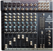
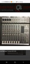
I have the abovementioned mixer. As is often the case, it is advertised as having more channels than it actually does, because, for instance, there are 4 channels with stereo inputs, which they count as 2 channels each, but are mixed at the input and treated as a single channel with only one set of controls. Looking at the control surface, you can see 8 channels, and that is what you get.
There are other shenanigans, too, like only one side of a headphone set working, or only one of the LED meter ladder pair tracking the mains, which makes no sense.
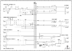
The manual, which is attached here, has large gaps in the information it provides, but it does contain both a schematic and a block diagram.
My ability to relate the physical controls to the schematic is limited. I do better with the block diagram. My problem is that even in the diagram, there appear to be points which are best described as "... and then magic happens ..." which is not good.
I am trying to figure out why the pair of LED meters do not track the main left and right outputs, as they would in every mixer I have ever encountered. From the block diagram, it appears that they should.
I am attaching images of the mixer as well, so you can see the physical controls (which is what I need to work with).
All of the controls, including the LED ladders, work if you set them in particular ways, so it's not a failed part, or at least it doesn't look that way.
Here is where I lose my way in the block diagram:
Looking at the "CTRL ROOM AND PHONES" section (lower right),
The switch at the upper left corner of that section is labeled "2TK to CTRL R". It selects either the main post fader outputs or the "2TK/stereo aux ret 2" (lower left of block diagram).
Where is the corresponding physical switch in the controls ?
From there, the signal travels to a DPST switch, which selects either the main post fader outputs or the "PFL/Solo" signal.
Where is this corresponding physical switch ?
Another switch above the DPST connects the right meter.
Where is this switch ?
There are other shenanigans, too, like only one side of a headphone set working, or only one of the LED meter ladder pair tracking the mains, which makes no sense.
The manual, which is attached here, has large gaps in the information it provides, but it does contain both a schematic and a block diagram.
My ability to relate the physical controls to the schematic is limited. I do better with the block diagram. My problem is that even in the diagram, there appear to be points which are best described as "... and then magic happens ..." which is not good.
I am trying to figure out why the pair of LED meters do not track the main left and right outputs, as they would in every mixer I have ever encountered. From the block diagram, it appears that they should.
I am attaching images of the mixer as well, so you can see the physical controls (which is what I need to work with).
All of the controls, including the LED ladders, work if you set them in particular ways, so it's not a failed part, or at least it doesn't look that way.
Here is where I lose my way in the block diagram:
Looking at the "CTRL ROOM AND PHONES" section (lower right),
The switch at the upper left corner of that section is labeled "2TK to CTRL R". It selects either the main post fader outputs or the "2TK/stereo aux ret 2" (lower left of block diagram).
Where is the corresponding physical switch in the controls ?
From there, the signal travels to a DPST switch, which selects either the main post fader outputs or the "PFL/Solo" signal.
Where is this corresponding physical switch ?
Another switch above the DPST connects the right meter.
Where is this switch ?