Continue to Site

Welcome to our site!

Electro Tech is an online community (with over 170,000 members) who enjoy talking about and building electronic circuits, projects and gadgets. To participate you need to register. Registration is free. Click here to register now.

  • Welcome to our site! Electro Tech is an online community (with over 170,000 members) who enjoy talking about and building electronic circuits, projects and gadgets. To participate you need to register. Registration is free. Click here to register now.

Rookie on car audio amp repair. Little help understanding circuit.

Status
Not open for further replies.

fastline

Member
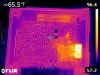
OK, more or less messing around with an old amp I had in the pile. Not even sure what the issue was with it but I threw some regulated power to it and it seemed to eat all the power I wanted to give it on the bench with no speakers or input signal. I rolled up to about 5 amps, then decided it would probably take all it could have so I better grab the thermal.

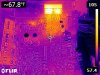
the FLIR image clearly pointed out a rather hot spot. Thinking "that was easy", I probed the mosfets and pulled em. Now I am second guessing what I am looking at, probably because I don't repair audio amps every often and don't fully understand them.

The FETs in the pic are 75344 power mosfets. Power it fed to them directly from input power. The issue is B+ is connected directly to the drain, and ground is plumbed right to the source....???? What am I missing here? You fire those dudes and you have a dead short..?

I sort of think I am on the right trail by following the hot spot with the thermal but not sure what to make of this. So far the mosfets seem good. No obvious short anyway.
 

Attachments

  • FLIR0192.jpg
    FLIR0192.jpg
    154.8 KB · Views: 139
  • FLIR0196.jpg
    FLIR0196.jpg
    175 KB · Views: 126
It's probably a boot converter, to step up the 12V from the battery to a voltage that will deliver more power into an 8R speaker. Are you sure the B+ goes straight to the drain, or is there a choke (like the big flat torroidal near the FETs) in circuit before it? Also, is there a large diode in the area, wired to the drain terminal?
If they're getting warm but don't appear to be short, it's possible that this section of the circuit is working. Check for other voltages on the big smoothing caps. If you have a short power stage, it will be dragging down the output of your boost converter and overloading it.
 
Indeed! Pardon my ignorance as I don't get into these often. Purely a learning project. The Bat+ goes to an inductor, then to the drain of the mosfet. The neg goes directly to the other side of the inductor as well as the source of the mosfets. These also go to a double power diode pack with heat sinking to the entire case.

Trying to learn on this. Is this a basic DC/DC converter configuration? I am trying to grasp as this thing works!111

I did however find the core issue which would be a pair of shorted output mosfets. This is a 2ch amp so has two identical channels. One is good, one is not. The pair that is bad are shorted all over themselves. They are a 28N15 and 36P15. Comparing back and forth, it was an easy find. I was also inspecting the gate drivers and seems everything is still intact. Diodes and only a 10Ohm(?) series resistor? There is quite a trail of components for the gate drive so I would have to draw that one out. I sort of wonder if the OEM had failed transistors in mind though. Seems a common failure mode.

So on the DC converter, is this designed to boost over 12V or just maintain voltage? Or does it possibly modulate voltage based on output requirements?
 
So on the DC converter, is this designed to boost over 12V or just maintain voltage? Or does it possibly modulate voltage based on output requirements?

It's to boost the voltage, the most you can get from a car battery is 4W to 4ohms, or 16 watts to 4 ohms for a bridged amplifier. In order to get more power you have to increase the supply voltage, that's why you have the DC converter.
 
LOL. V=IR. I need to pull my head out apparently.

So is the voltage constant or is this precisely how the output voltage is varied? Boost converter mosfets control the variable DC voltage to the output mosfets?


Hey, not trying to dip more into my ignorance as I probably need to know more about the impedance on the speakers but as I understand it, the DC resistance on the speaker coil could be used for a worst (or best) case scenario for power capability.

If you consider say 12V on a 4ohm load, that is 12/4 = 3A*12V = 36W? Where did your values come from?
 
Last edited:
LOL. V=IR. I need to pull my head out apparently.

So is the voltage constant or is this precisely how the output voltage is varied? Boost converter mosfets control the variable DC voltage to the output mosfets?

No, it generates a fixed voltage, and more often than not a spilt supply using a small transformer - depending on the power required, +/-25 to 30V is common.

Hey, not trying to dip more into my ignorance as I probably need to know more about the impedance on the speakers but as I understand it, the DC resistance on the speaker coil could be used for a worst (or best) case scenario for power capability.

If you consider say 12V on a 4ohm load, that is 12/4 = 3A*12V = 36W? Where did your values come from?

That would be for a resistor directly across the battery - RMS power works out about 4W, assuming average losses in the amplifier.

Assuming small losses you get about 4V RMS out of a 12V supply, square that (16V) and divide by the speaker impedance (4 ohms) gives 4W - and this was the 'honest' rating given to car radios.
 
You can get around 8 V RMS from a 12 V supply if you have a full bridge output, where the two speaker connections are driven in anti-phase. That gives you around 16 W into 4 Ω. That is the limit without a boost converter or lower resistance speakers.
 
4W RMS is the maximum output before clipping. With 10% distortion it is clipping but not too badly and the power is about 5.2W. If it is clipping its head off so the output is a squarewave then it is 8W, manufacurers call it "maximum power".
 
As regards the DC-DC, haver a look at the Wikipedia page on the boost converter:
https://en.wikipedia.org/wiki/Boost_converter
it probably explains it better than I could.

Your tracing of the circuit doesn't quite make sense:
The Bat+ goes to an inductor, then to the drain of the mosfet. The neg goes directly to the other side of the inductor as well as the source of the mosfets.
as that puts the indictor directly accross the battery. Quite likly it's a transformer as Nigel mentions in #6, and so that's two different windings you're looking at.

So... have you removed the shorted MOSFETs and does the other channel now work (or are you at least getting some sensible voltage out of the DC-DC)?

Out of interest (because I've never taken one of these apart either) do you believe it's a class D (switching) output or a conventional AB? My experience of switchers and FET drive suggestes that if the gate resistor and other components in the gate-drive circuit are intact then the driver IC has probably survived, but then it's often not a lot of trouble to change them anyway.

I really want one of these thermal imagers, by the way!
 
Status
Not open for further replies.

New Articles From Microcontroller Tips

Back
Top