Continue to Site

Welcome to our site!

Electro Tech is an online community (with over 170,000 members) who enjoy talking about and building electronic circuits, projects and gadgets. To participate you need to register. Registration is free. Click here to register now.

  • Welcome to our site! Electro Tech is an online community (with over 170,000 members) who enjoy talking about and building electronic circuits, projects and gadgets. To participate you need to register. Registration is free. Click here to register now.

Roof LED's

Status
Not open for further replies.

jrz126

Active Member
I'm going to use this topic to post the questions I have for my Roof Led project here.

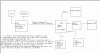
I came up with this block diagram to try to sort things out.

My first question is kinda simple, for the serial connection between micros, what kind of cable will I need to use? and can I just connect the 2 directly, or do I need those max232 chips?

My package of goodies is in town, and it says it's out for delivery, but the scheduled delivery date according to UPS is tomorrow. I better not have to wait. It feels like Christmas when I was younger... :D
 

Attachments

  • block_diagram_124.jpg
    block_diagram_124.jpg
    83.8 KB · Views: 1,015
jrz126 said:
My first question is kinda simple, for the serial connection between micros, what kind of cable will I need to use? and can I just connect the 2 directly, or do I need those max232 chips?

You can connect them directly, although I would advise you to use screened cable as it's running in a noisey environment.
 
A 1 wire LIN interface is not all that difficult to implement. Microchip has LIN interface chips, but you can do basic functionality with just some transistors.

You might not want to add even that complexity to it, if a regular 2 wire serial connection is working fine.
 
You don't need a max232 chip since there is no need to change the voltage to the funky rs232 standard levels.

Do you need to only transmit from one side to the other, or is it two-way communication?

It's also possible to use I2C which handles bidirectional comm on two wires, but you'd be deviating from the standard due to the cable length involved. By the spec, cable capacitance will be exceeded after just a few feet, but the PIC's pin's driving capabilities are much higher.

You probably want to look at how many wires are involved since a thinner cable is easier to route. Also putting the ends into screwclamp terminal strips (like Phoenix) will save you from having to do something like DB-9 which would have to be assembled on the car itself unless you can avoid the need to run the cable through small holes.
 
It's 2 way communication. I'm trying to figure out what type of communication I need to use (I2C, serial, ect.) I'm brand new to pics, so I dont know much about them. I've got plenty of room to route the cables I'm probably going to use those headers and sockets (0.1" pin spacing, like a hard drive connector.)

Nigel Goodwin said:
You can connect them directly, although I would advise you to use screened cable as it's running in a noisey environment.

So I will be able to directly connet them with a shielded cable over a 25 ft. span. (that's the maximum length it would be). How many wires would that be? and what kind of shielding should I look for? The shield just connects to the chassis ground?

Monkeyman87 said:
LOL I know what you mean

Now It's even worse, I just checked on UPS.com and it says it was delivered at 11:30 this morning, and I'm stuck at work until 5 :cry: . I'm going to see if they need me to do anything (usually they don't, so I just spend most of my time on here), and if not I'll say that I have to go to an extra help session at school.
 
LIN is really made for this. It's an automotive 1 wire interface. It's pretty much just serial communications, but it's level shifted to 12v and protects the uC from shorts. It has a special protocol (which you can ignore most of if it's it's just 2 nodes) which allows multiple nodes on the line, and avoid collissions from more than one node talking at once. Microchip has plenty of LIN stuff, including app notes.

I've half implemented a LIN interface with a few modules on my racecar.

If it's simple direct connect serial, then you're using 2 wires, transmit and receive. Simply connect transmit to receive and the opposite.
 
I'll have to look into the LIN. my 16f628A's were shipped on the 20th, they'll be here by the 25th so I can start tinkering.

on a side note, I left work early to use my new stuff from digikey. I ordered some 4' lengths of heatshrink tubing. I thought they would be on a roll or something...nope, the bow was 4 feet long. I'm glad I didnt order a 25' length of it.

I connected some LEDs up to the 82 ohm resistors I bought and those are unbeleivably bright. I think I'm going to need to make some sort of dimmer control for them. I was thinking of maybe an adjustable Vreg. I'll have to look into how the voltage is adjusted on them, because I would want to control the brightness using my keypad. I'm thinking of a digital pot.? any suggestions?
 
LIN is interesting, but not a big advantage to you if you're only communicating between the 2 devices. It gets interesting though, if you want to hook the LCD/keypad controller up to other modules that, control door poppers, run other lighting effects, horn tunes, or any other show car controls. You can have multiple modules around the car running different things, and controllerd by the one keypad/LCD unit.

If you were running the LED's directly from the uC, you could use PWM for full control of the brightness, but with your added hardware, I have no idea.
 
How hard would it be to upgrade from a regular direct connection between 2 pics to a LIN interface? I'm thinking since I got enough on my plate to keep me busy, so to simplify it a little, I'll just do a regular direct connection between pics. But I dont want to limit myself to any future upgrades. Although I might as well do it since I'm making PCBs for everything, and I know I wont want to redo them.

As for the dimmer,
Here's what I'm doing: the 8 bits of the Shift registers are connected to a ULN2803 (high current driver IC) when +5V is applied to the input, the corresponding output is brought low completing the circuit.

Then I'm using 2 Vregs to give the leds the power (32 leds per Vreg, 20 mA apiece, = 640mA per regulator). Now I'm thinking that a simple solution would be to use an adjustable V-reg, (I'm not sure how they are adjusted, I'm assuming a resistor does the adjustments), if it is a resistor, I just connect a digital potentiometer and use my micro to control it.

Now a slightly more complicated idea would be to make an external PWM supply for the +5V for LED's. But I'm not sure as to what all this would involve.

Yet another solution would be to pulse the output enable of the Shift registers, which would then pulse the ULN2803s. Both the SR's and 2803s have quick turn on/off max times, so that would not be a problem (I think)2803s: 1us max (.25 us typical).
74hct299: output enable high outputs: 39ns (18ns typical) low outputs 33ns (15ns typical)
output disable time: high outputs: 46ns (24ns typ) low outputs: 39ns (20ns typical).
A downside to this is that I was planning on pulsing the OE for different patterns ect, so I would use this as a very last resort.

So this just added another problem to the mix, I think I'm in way over my head here, and I kinda like it :?
 
It's best if you look at the app notes on Microchip site.

I'm using a Microchip hardware interface for LIN. I think it's the MCP201. I'd have to double check. I remember in an appnote, it was shown you could do the hardware layer with just 2 transistors. Maybe it was a Atmel appnote. I'll try to find it.

Application Notes
AN235 - Implementing a LIN Master Node Driver on a PIC18 Microcontroller with USART
AN237 - Implementing a LIN Slave Node on a PIC16F73
AN239 - Bit Banged LIN Slave Node for PIC16 & PIC18
AN240 - LIN Slave Node on a PIC16C433
AN864 - Implementing a LIN Slave Node on a PIC18F1320
 
I think I'm going to go with the LIN interface. There are a few other things that I will want to add later, how complicated will it be to add another micro to the lin interface? These added functions will be controlled by the keypad micro. So I know that it will have to be reprogrammed, but will I have to reprogram all the other micros so that this new one will work?

Also, how can I shift the data into the shift registers? When I was going to use the AVR micro, there was an app note that used the MOSI MISO SCK pins to shift the data. I dont know if these are the exact pins or not, but it didnt use just a regular data pin. Can I just use a regular data pin on the PIC, (say port A.3)? Or do I need a different method? (I2C?) How many I2C connections can you have per PIC?

I got my 628A samples a couple days ago, so I'm going to start playing with Nigel's tutorials. My 877A's wont be here for another month! :( I guess I cant be mad about that though, they were free :p

I've decided to not bother with a dimmer, I have the leds installed and they are just about the perfect brightness.

one more thing, is it helpful to have the entire datasheet for the micro printed out? It's quite a few pages, so I dont want to print it if it won't be of any use. Are there any other good online references that are helpful?
(I would print it at school of course, At least I get something worthwhile for my $4000.00 a semester :wink: )
 
how many mA does it takes to light up one led..about 20mA will be enough to light an LED so the resistor u used is too low , i guess..does the led's get hot...make it 470 ohms or 680 ohm's something like this...it will be safe ..
for shiftregisters i say use 74hc595 which is best for that project....i have tested it..
**broken link removed**

this link will have tested asm code for shiftregister
 
Thanks for the code, I'm going to give it a try when I get home tonight. Is there any limit to the speed at which I can shift the bits?

About my current limiting resistors...
I would need the 470 ohm if i were running the led's at the car battery voltage. That would give me a voltage drop of 10.2V across each resistor (assuming 13.6V). Which at 20mA the resistor would disipate .204 Watts, multiply that by 62 leds = 12.648 W.

Instead what I'm doing is using the 5V regulator (7805) to drop the voltage down to 5V then I use a 82 ohm resistor. the power disipated by a resistor now is 0.032W and with the 62 led's it's 1.984 W total in the series resistors.
Now you might be thinking that the power saved by dropping it down to 5V is being put into the Vreg's. which it is, but I have a large cpu heatsink with a fan on it that will keep the vregs plenty cool.

So in the end I can use an 1/8W resistor for my 62 current limiting resistors. and I can use the old CPU heatsink for the Vregs, which makes the whole project look that much cooler when I'm showing it off.
 
Status
Not open for further replies.

Latest threads

New Articles From Microcontroller Tips

Back
Top