Jean-Francois Bilodeau
New Member
Hello everyone.
Since this is my first post, I'll introduce myself : I'm a 19 years old student from Quebec City. I'm studying programmable electronics and robotics at Cégep Limoilou. I'm a real electronic accro and I love doing projects on the side while studying. Here's one of these projects :
A complete Robot built around a Ds89C450 MCU and controlled by a bluetooth Super Nintendo controller handled by a PIC16F88.
The robot is a 4WD model from RobotShop.com. The code is free to be used by anyone if it can actually help anyone
Worklog #1 : The bluetooth controller
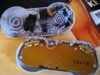
The controller by itself is pretty nice. I've took apart a certified SuperNintendo controller to look at what wat actually inside. Since I saw 3 output lines and 16 input lines from the V520B chip, I've came to the conclusions that it might be a 16 bit PISO (Paralell-In/Serial-Out) shift register! I've took my logic analyzer and BAM! That was it, I was able to the decode the timings of the chip and actually re-create them with a PIC.
With the help of a PIC16F88, I've made a small ASM program which handles the shift register and then sends the datas via the internal UART (no Max232 used neither RS232, simple 0-5V logic). The PIC actually fits INSIDE the controller, so this is going to be a complete handheld, wireless controller. The test setup was done with the second mcu(dallas) with a serial reception routine and was actually able to see the buttons registers, one by one when I was pressing them. Since this setup used cables to TX the datas from the PIC, I've decided to buy a bluetooth transceiver from Ebay(HC-05 master/slave mode) which I havn't received yet, and use it to handle the data transmission. The transceiver also fits inside the controller (micro-scopic dimensions), so yeah the controller is going to be bluetooth.
Here is the code for the PIC part, fully documented. Feel free to give me your impressions. I've also got a small video which I will upload in the next minutes.


Since this is my first post, I'll introduce myself : I'm a 19 years old student from Quebec City. I'm studying programmable electronics and robotics at Cégep Limoilou. I'm a real electronic accro and I love doing projects on the side while studying. Here's one of these projects :
A complete Robot built around a Ds89C450 MCU and controlled by a bluetooth Super Nintendo controller handled by a PIC16F88.
The robot is a 4WD model from RobotShop.com. The code is free to be used by anyone if it can actually help anyone
Worklog #1 : The bluetooth controller
The controller by itself is pretty nice. I've took apart a certified SuperNintendo controller to look at what wat actually inside. Since I saw 3 output lines and 16 input lines from the V520B chip, I've came to the conclusions that it might be a 16 bit PISO (Paralell-In/Serial-Out) shift register! I've took my logic analyzer and BAM! That was it, I was able to the decode the timings of the chip and actually re-create them with a PIC.
With the help of a PIC16F88, I've made a small ASM program which handles the shift register and then sends the datas via the internal UART (no Max232 used neither RS232, simple 0-5V logic). The PIC actually fits INSIDE the controller, so this is going to be a complete handheld, wireless controller. The test setup was done with the second mcu(dallas) with a serial reception routine and was actually able to see the buttons registers, one by one when I was pressing them. Since this setup used cables to TX the datas from the PIC, I've decided to buy a bluetooth transceiver from Ebay(HC-05 master/slave mode) which I havn't received yet, and use it to handle the data transmission. The transceiver also fits inside the controller (micro-scopic dimensions), so yeah the controller is going to be bluetooth.
Here is the code for the PIC part, fully documented. Feel free to give me your impressions. I've also got a small video which I will upload in the next minutes.
Code:
;******************************************************************************
;                                                                             *
;    Filename:      RobotController                                           *
;    Date:          January 6th, 2014                                         *
;    File Version:                                                            *
;                                                                             *
;    Author:     Jean-Francois Bilodeau                                       *
;    Company:                                                                 *
;                                                                             *
;                                                                             *
;******************************************************************************
;                                                                             *
;    Files required:                                                          *
;             P16F88.INC                                                      *
;                                                                             *
;                                                                             *
;******************************************************************************
;    Code explanation :
;
;    This code gives you the chance to create yourself a bluetooth SNES
;    controller. Essentially, what it does is handling the serial output of the
;    16bit SIPO shift register (V520B) which is inside the controller.
;    Each 16ms, the PIC sends a 12us HIGH pulse on the latch PIN of the shift
;    register, giving him the chance to latch the states of the buttons.
;    Right after this, the serial data get's out of the shift register, so I
;    transmit the 1st button and then sends a 6us, 50% duty cycle clock on the
;    clock pin of the shift register, letting the chance to serialize the 12
;    buttons from the snes controller. This means that I've handled the
;    registers of the PIC UART, and the functions are below and easy to use.
;
;    Use th TX pin from the PIC to see the data that get's out of the
;    controller. I use these with a HC-05 bluetooth transmitter and another
;    HC-05 receiver on another micro-controller to receive the data sent by the
;    PIC. I can now receive a standardized 16bit serial data on another
;    IC to process the state of the buttons and then act as required to control
;    my robot. Hope this can be helpful for you.
;    Thanks.            -- Jean-Francois Bilodeau--
;******************************************************************************

;***********************PIC16F88 Schematic*******************************
;
;                     IN  IN  S3  IN      S2  S1  TX  D2            S: Switch
;                     A1  A0  A7  A6 VDD  B7  B6  B5  B4
;                    ____________________________________
;           PIN     | 18  17  16  15  14  13  12  11  10 |
;                   |               16F88                |
;           PIN     | 1   2   3  _4_  5   6   7   8   9  |
;                    ------------------------------------
;                     A2  A3  A4  A5 VSS  B0  B1  B2  B3
;                     IN  IN  IN  MCL     SCL SDA RX  D1            D: Del
;
;******************************************************************************


;******************** Fonctions used *********************************
; InitPic                      ; Initialise the PIC.
; InitRs232                    ; Initialise the UART registers
; TX232                     ; Send a data via UART
; GetBouton                    ; Latch chip state, send data to PIC
; Delay16s                     ; Delay to handle internal shift register
;******************************************************************************


   LIST      p=16f88           ; list directive to define processor
   #include <p16F88.inc>       ; processor specific variable definitions

;  errorlevel  -302             ; suppress message 302 from list file

  __CONFIG    _CONFIG1, _CP_OFF & _CCP1_RB0 & _DEBUG_OFF & _WRT_PROTECT_OFF & _CPD_OFF & _LVP_OFF & _BODEN_ON & _MCLR_ON & _PWRTE_ON & _WDT_OFF & _INTRC_IO

  __CONFIG    _CONFIG2, _IESO_OFF & _FCMEN_OFF


#define   BANK0   bcf   STATUS,RP0;
#define   BANK1   bsf   STATUS,RP0;

#define SCL PORTB,0
#define SDA PORTB,1

#define SW1  PORTB,6
#define SW2  PORTB,7
#define SW3  PORTA,7

#define LATCH PORTA,3
#define RXBTN PORTA,4
#define PULSE PORTA,2


#define DEL1 PORTB,3
#define DEL2 PORTB,4


;***** VARIABLE DEFINITIONS  **************************************************
;w_temp        EQU     0x71     ; variable used for context saving
;status_temp   EQU     0x72     ; variable used for context saving
;pclath_temp   EQU     0x73     ; variable used for context saving


;VARIABLES  EQU     0x20     ; Variables here
  CBLOCK  0x20
    vReceive                    ;Rs232 receive variable
    vDelay1                        ;Delay1 counter
    vDelay2                        ;Delay2 counter
    vBoutonSend                    ;16 time loop var
    vTxBtn                        ;Contains button status
  endc


;*************************Reset vector*************************************
        ORG     0x000          ; Processor reset vector
        clrf    PCLATH         ; Page 0 (BootLoader)
        goto    Main           ;


;***********************Interrupt vector********************************
        ORG     0x004          ; Interrupt vector location
        goto    Interrupt


;***********************MAIN ROUTINES***********************************

Main
    call     InitPic            ;Initialise the PIC16F88
    call     InitRS232       ;Initialise the UART
Loop
    call     GetBouton        ;Get the boutons statuses
    goto     Loop            ;Do this FOREVER


;****************************** SubRoutines **************************************


;**************************** InitPic *****************************************
;       Fnct name : InitPic
;       Author : Jean-Francois Bilodeau
;       Creation date : January6th, 2014
;       Description :      Initialise the PIC
;                          - RP1 = 0 , so we're always in BANK0 or BANK1
;                          - Deactivate interrupts sources
;                          - Deactivate analog inputs
;                          - PORTA : RXBTN input, LATCH output, PULSE output
;                          - PORTB : TX as output, RX as input
;
;       Called functions: None
;       Input parameters : None
;       Output parameters : None
;       Used variables : None
;       Include :               16F88.inc
;       Equates :
;       #Defines :              BANK0   bcf   STATUS,RP0;
;                               BANK1   bsf   STATUS,RP0;
;
;******************************************************************************
InitPic

     bcf     STATUS, RP1    ; Get sure BANK0 or BANK1
     BANK1                  ; Select Bank1
     bcf     INTCON,GIE     ; Deactivate interrupts
     clrf    ANSEL          ; Deactivate ANALOG inputs

     movlw   b'01111000'    ; osc internal 8 Mhz
     movwf   OSCCON            ;

     movlw   b'11110011'    ; 1=INPUT, 0=OUTPUT
     movwf   TRISA          ; RXBTN INPUT, LATCH OUTPUT, PULSE OUTPUT

     movlw   b'11100100'    ; Tx = output, RX = input
     movwf   TRISB
     BANK0
     return

;*** End INITPIC ******************************************************


;******************************GetBouton***************************************
;  Function name : GetBouton
;  Author : Jean-Francois Bilodeau
;  Creation date : January 3rd, 2014
;  Description :Interface for the snes controller
;                Each 16ms, Latch on P3_2 which prepares the internal SNES chip
;                When chip ready, store btn status from P3_4, then pulse on
;                P3_3 to get the next btn status. When a data is received,
;                we send it through a serial port.
;                Boutons table
;                /B/Y/Select/Start/Up/Down/Left/Right/A/X/LTrig/RTrig
;                Means 12 pulses on P3_3 and 12 datas to send via serial UART
;
;
;  Called functions:    Tx232
;                        Delay16ms
;                        Delay12us
;                        Delay6us
;  Input parameters : None
;  Output parameters : Bouton from the snes controller via UART
;******************************************************************************
GetBouton
    movlw   b'11110011'    ; PORTA Inputs/Outputs
    movwf   TRISA          ; RXBTN Input, LATCH Output, PULSE Output

    call     Delay16ms    ;1 sec done???
    bcf        LATCH        ;Get sure it's down
    bsf        LATCH        ;Latch internal chip
    call     Delay12us    ;12US high
    bcf        LATCH        ;Latch done
    movlw    .17            ;16 for the 12 boutons + 4 leftover
    movwf    vBoutonSend    ;Lets make a for loop

Bouton16                ;Loop 16 times
    decfsz    vBoutonSend    ;Decrem, skip if result = 0
    goto     SendBouton    ;Each time a btn is received
    goto    EndSendBouton;16 time done? Yeah right

SendBouton
    btfsc    RXBTN        ;Bouton received?(Input)
    goto    Tx1            ;If not pressed
    goto    Tx0            ;If pressed

Tx1 ;SAVE BOUTON STATE = 1
    movlw    0x31        ;Store 31 in W register
    movwf    vTxBtn        ;W into variable
    goto     NextBouton    ;Next bouton ready

Tx0 ;SAVE BOUTON STATE = 0
    movlw    0x30        ;Store 30 in W register
    movwf    vTxBtn        ;W into variable
    goto    NextBouton    ;Next bouton ready

NextBouton
    bsf        PULSE        ;Clock for Shift Register
    call    Delay6us    ;Stabilisation delay
    bcf        PULSE        ;
    call    Delay6us
;TX SERIAL
    movf    vTxBtn,W    ;vTxBtn into W
    call    Tx232        ;Send it through UART
    goto    Bouton16    ;Do this for the 12 buttons

EndSendBouton
    return                ;END


;****************************** Delays **************************************
;  Function name : Multiple Delays
;  Author : Jean-Francois Bilodeau
;  Creation date : January 4th, 2014
;  Description :   Multiple delays useful for this program
;  Delay formulas : 8Mhz oscillator
;                    4 cycle/instructions, 1 instruction = 1us
;******************************************************************************
Delay16ms
    movlw    .255        ;255 in w
    movwf    vDelay1        ;255 in Delai1
    movlw    .40            ;40 in w
    movwf    vDelay2        ;40 in Delai2

Compte1
    decfsz    vDelay1        ;Dec Delay skip if result = 0
    goto    Compte1        ;Result = 1, restart
    movlw    .255        ;Reload var value
    movwf    vDelay1        ;Put it back into vDelai1
    goto    Compte2        ;Next compt
Compte2
    decfsz    vDelay2        ;Dec the second delay
    goto     Compte1        ;Result=1, restart the whole thing
    return                ;Retourne

Delay12us
    nop
    nop
    nop
    nop
    nop
    nop
    nop
    nop
    nop
    nop
    nop
    nop
    nop
    nop
    nop
    nop
    nop
    nop
    nop
    return

Delay6us
    nop
    nop
    nop
    nop
    nop
    return
;End delay's routines *************************************************

;--------------------------UART FUNCTIONS-----------------------------

;ALWAYS BE SURE THAT YOU'VE INITIALISED THE INITRS232 FUNCTION BEFORE
;USING THESE FUNCTIONS, OTHERWISE THEY WON'T WORK

;************************  Rx232  *************************************
; Function name : Rx232         Author: Pierre Chouinard  10-10-2009
; Description : Reads RX from PORTB,2
;               Doesn't work as an INTERRUPT
;
;
; Includes:
;     #include <p16F88.inc>
;
; Input parameters     : None
; Output parameters    : w & vReceive: Contains received character.
;
;**********************************************************************
Rx232
    BANKSEL PIR1    ;
    btfss PIR1,RCIF ; Wait to receive something from UART
    goto  Rx232     ;
Rx232Go             ; Something received
    movf  RCREG,W   ; Register status into W
    movwf vReceive  ; Puts the character into vReceive
    return          ;
;
;--End Rx232  ------------------------------------------------

;************************  Tx232  *************************************
; Function name : Tx232          Author: Pierre Chouinard  10-10-2009
; Description : Transmit data via UART
;               TX = PORTB,5  (RX = PORTB,2)
;
; Includes:
;     #include <p16F88.inc>
;
; Input parameters: W contains the data to SEND (vTxBtn in GetBouton)
; Output parameters : None
;
;**********************************************************************
Tx232
    BANKSEL PIR1
    btfss  PIR1,TXIF ; Wait for previous transmit to be done
    goto   Tx232     ;
    movwf  TXREG     ; Transmit the character
    return           ;

;-- End TX232  ------------------------------------------------

;**************************** InitRS232 *******************************
; Function name : InitRS232     Author : Pierre Chouinard 10-10-2009
; Modifications & Adaptations : Jean-Francois Bilodeau    06-01-2014
; Description : Initialise the UART registers to send & receive data
;               on the PIC16F88 at 57600bds TX=PORTB,5 RX=PORTB,2
;
; Includes
;     #include <p16F88.inc>
;     #define   BANK0   bcf   STATUS,RP0;
;     #define   BANK1   bsf   STATUS,RP0;
;
; Input parameters: None
; Output parameters : None
;
;**********************************************************************
InitRS232
    movlw   b'10010000'; Set receive on UART
    movwf   RCSTA      ; CREN = 1, SREN = 1
    BANK1              ;

    movlw    b'00100100'; BRGH = 1, TXEN=1
    movwf   TXSTA      ; Sets the Transmit register

    movlw    .8           ; 57600 bds
    movwf   SPBRG      ; 8000000/(16*19200)-1
    BANK0              ; 16=BRGH=1
    return             ; 64=BRGH=0


;*** Interrupt **************************************************

Interrupt

;       movwf   w_temp            ; save off current W register contents
;       movf    STATUS,w          ; move STATUS register into W register
;       movwf   status_temp       ; save off contents of STATUS register
;       movf    PCLATH,W          ; move PCLATH register into W register
;       movwf   pclath_temp       ; save off contents of PCLATH register

; isr code can go here or be located as a call subroutine elsewhere


;       movf    pclath_temp,w     ; retrieve copy of PCLATH register
;       movwf   PCLATH            ; restore pre-isr PCLATH register contents
;       movf    status_temp,w     ; retrieve copy of STATUS register
;       movwf   STATUS            ; restore pre-isr STATUS register contents
;       swapf   w_temp,f
;       swapf   w_temp,w          ; restore pre-isr W register contents
        retfie                    ; return from interrupt

; *********************************************

        END                       ; directive 'end of program'
Last edited:
") All code can be messy or beautiful. It all depends on the skills of the programmer.
All code can be messy or beautiful. It all depends on the skills of the programmer.