Continue to Site

Welcome to our site!

Electro Tech is an online community (with over 170,000 members) who enjoy talking about and building electronic circuits, projects and gadgets. To participate you need to register. Registration is free. Click here to register now.

  • Welcome to our site! Electro Tech is an online community (with over 170,000 members) who enjoy talking about and building electronic circuits, projects and gadgets. To participate you need to register. Registration is free. Click here to register now.

ring counter circuit

Status
Not open for further replies.

neptune

Member
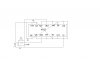
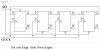
i have made a ring counter ot of 4013 ic .

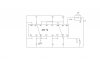
i connected a manuall switch to clock circuit (S). because i want to manually control the ring. when s is pressed clk circuit generates a pulse which is input to 4013 . so L1 should be on and L2 off

at another press L1 off and L2 on.
for startig this circuit i connect Q1 to high and then disconnect it.

problem is that both L1 and L2 are on .

HELP
 

Attachments

  • 4013 ring.jpg
    4013 ring.jpg
    43.4 KB · Views: 1,282
Not a very clear diagram. But here are some things I see wrong with it:
Q1~ and Q2~ should NOT be tied to Vss.
L1 and L2 (LEDs?) should have current limiting resistors. Try 1K.
Your clocking/Power switch circuit makes no sense. You need a steady 9V on Vdd. Then you also need to debounce the switch before feeding it into the clock input of the 4013.
 
oh sorry there was a mistake !!!!
i connected vdd to manuall switch.
i should connect permanently to vdd.
i think q~ should be grounded.
so,for the rest of the part the logic of circuit is wright.
 
oh sorry there was a mistake !!!!
i connected vdd to manuall switch.
i should connect permanently to vdd.
i think q~ should be grounded.
so,for the rest of the part the logic of circuit is wright.

How many times must we tell you, you must not ground or connect directly to +Vsupply any of the 4013 OUTPUTS.

As I explained yesterday on the Chat line, your not circuit is not right...
 
Last edited:
Hi neptune,

here is a sequence of screenshots using all four outputs of a 4013. There are always two outputs high and two are low.

Compare the pictures and select what you want. The input circuit is a debouncer circuit.

Boncuk
 

Attachments

  • 4013-1.gif
    4013-1.gif
    12.3 KB · Views: 712
  • 4013-2.gif
    4013-2.gif
    12.3 KB · Views: 380
  • 4013-3.gif
    4013-3.gif
    12.3 KB · Views: 354
  • 4013-4.gif
    4013-4.gif
    12.3 KB · Views: 390
How many times must we tell you, you must not ground or connect directly to +Vsupply any of the 4013 OUTPUTS.

Hi Eric,

he can't read your post because of heavy smoke development from the circuit. :D

Hans
 
Hi Eric,

he can't read your post because of heavy smoke development from the circuit. :D

Hans

hi Hans,
I discussed this circuit with him yesterday, in detail, on the chat line.

'agu' has also told him the same thing on his other 4013 thread.
 
ok, where then should i connect the unsed pins
 
Hi Eric,

he can't read your post because of heavy smoke development from the circuit. :D

Hans

ha ha very funny...
may be i am not smarter then u guys.
but atleast im trying.:eek:
 
good now thats a clear answer...
 
good now thats a clear answer...

hi neptune,
My concern is that if you have been running the 4013 wired in that configuration, the 4013 may have died, so you may not get the operation you are expecting.:)
 
no i dont connect anything , physically test the circuit, before knowing it.

also one thing "boncuk" circuit is not a ring counter.
he has connected q1 to clk2. but in circuit clk is common for alld f/f
 

Attachments

  • 04431.jpg
    04431.jpg
    21 KB · Views: 280
no i dont connect anything , physically test the circuit, before knowing it.

also one thing "boncuk" circuit is not a ring counter.
he has connected q1 to clk2. but in circuit clk is common for alld f/f

hi,
Thats good.

Please post the LED sequence you want as the switch is pushed.?
 
here is the schematic of circuit. using 40174 hex d f/f IC.
the switch connected is manual. manually press the switch and ring will run.

i connected d1 to logic high for starting this circuit.

problem is that all of the led's are on irrespective of where i conectd the d1 input.
 

Attachments

  • 40174ring.jpg
    40174ring.jpg
    44 KB · Views: 457
oh man there is no reply

i have been waiting for weeks
 
Status
Not open for further replies.

Latest threads

New Articles From Microcontroller Tips

Back
Top