Continue to Site

Welcome to our site!

Electro Tech is an online community (with over 170,000 members) who enjoy talking about and building electronic circuits, projects and gadgets. To participate you need to register. Registration is free. Click here to register now.

  • Welcome to our site! Electro Tech is an online community (with over 170,000 members) who enjoy talking about and building electronic circuits, projects and gadgets. To participate you need to register. Registration is free. Click here to register now.

RGB Controller

Status
Not open for further replies.

RodneyB

Member
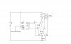
I Have attached a diagram of an RGB controller I am trying to build.

When I apply power the green and Blue LED in the tri colour LED seem to glow but nothing happens.

I am cncerned about my transistor switching on the LED from the CD4029 orginally the circuit required a common Cathode LED but I could not find any so adjusted the circuit as I thought correct.

I have found the 4029 gets warm not HOT and nothing happens.

are the transistors switch the LED's correct ?

How can I build a simple circuit to switch a single led, from the 4029 this would enable me to check if the IC is faulty.

Many thanks

Rodney
 

Attachments

  • RGB controller.jpg
    RGB controller.jpg
    52.9 KB · Views: 165
hi,
Pin #5 is an Input, as are 12,13, 3 , so they are open circuit 'floating' ,, connect them to 0V.

EDIT:

Added a simulation for you. Shortened the 1sec rate for SIM ONLY.
 

Attachments

  • AAesp03.gif
    AAesp03.gif
    36.5 KB · Views: 170
Last edited:
Thanks for the advice! before I try this, is it possible for me to drive the LED directly from the output of the 4029 just for testing purposes.

Once I have it working then I can add the Transistors to the output, this will enable me to drive several LED's at once. The Purpose of the Capacitor on the base is to produce a fading effect so I can get diffarent colours from the Tri Colour LED.

hi,
What are the details of the LED's. ie: current rating.??

The datasheet for the4029 shows only approx 2mA at a 12V supply.
 

Attachments

  • AAesp04.gif
    AAesp04.gif
    21 KB · Views: 157
The Purpose of the Capacitor on the base is to produce a fading effect so I can get diffarent colours from the Tri Colour LED.

The capacitors will only delay the transistor switching on. Once the capacitor reaches 0.7V the transistor will turn on. I assume this is why Eric left them off his diagram.

Mike.
 
Just wire the 10 k resistors straight to the cathodes of the LED. This will provide a usable indication although it will be inverted from what the transistors will show.
By the way, I don't believe the 4029 should get warm.
 
Thanks Very Much for all the advice I have now got the LED's Switching on But there is no single distinct colour. I seem to have a mixture of Red and Green and Blue. Do I need to have diffarent resistors for each of the LEDs on the tri colour LED?
 
Just wire the 10 k resistors straight to the cathodes of the LED. This will provide a usable indication although it will be inverted from what the transistors will show.
By the way, I don't believe the 4029 should get warm.

I did this and hey presto I get red, gren red green no problem BUT no Blue
 
Blue LEDs tend to have a forward voltage of around 3V and so need a smaller resistor. If you post a link to the data sheet then someone will work out how to calculate the value.

Mike.
 
Thank you. I dont have a data sheet bought from our local supplier and can guarantee its the cheapest one from china Like everything in Zimbabwe
 
Thank you. I dont have a data sheet bought from our local supplier and can guarantee its the cheapest one from china Like everything in Zimbabwe

hi,
Use a 470 ohm resistor from +12V to the Blue LED Anode and the Cathode to 0V, to TEST the Blue LED.
 

Attachments

  • LEDfwd1.gif
    LEDfwd1.gif
    6.1 KB · Views: 148
Last edited:
I dont seem to be making any progress with this project. Q3 (Pin 14) goes high every second Pulse. I have tried 3 seperate IC's and the same result. After several pulses the output goes high and stays high. I am at a total loss as to where to go from here.
 
I dont seem to be making any progress with this project. Q3 (Pin 14) goes high every second Pulse. I have tried 3 seperate IC's and the same result. After several pulses the output goes high and stays high. I am at a total loss as to where to go from here.

hi,
What is the 1.5s pulse source.?

Manual push button or logic. etc??

Is your 12V power supply decoupled on on the project board, using say 100nF and 47uF capacitors.

Post your latest circuit diagram

EDIT: I see its a 555 timer clock, the diagram is not very clear. Is it a 12V pulse.?
 
BNG.jpg

I have changed the clock pulse to 0.5 seconds.

Pins
12 - B
13 - c
3 - d
5 - Cl

Are all held low

Pins

4 - A
9 - B/D (dont know how to put the line above the D)
10 - U/D (dont know how to put the line above the D)

Pins 2 (QD)
Pin 1 (PE) joined

Pin 7 N/C

I have used High bright LED's Red.

All I am getting is The LED's on the outputs 11 and ^ coming on which appears randomly. I am going to try and do a truth table to send later.
 
hi Rodney,
That should work as you have explained it.?

I assume pins, 4,9 and 10 are connected to +12V.? and pins 12,13 and 3 are connected to 0v.??

Do you have the 4029 pin 16 to +12V and pin 8 to 0v.???

What are the values of the LED resistors.?

Are you sure that your 555 timer is running at 0.5Sec ??

E
 
Hi

Pins 4,9 and 10 are connectd to the +12 Volts

Pins 12, 12 and 3 are connected to the 0v

Pin 16 is connected +12V

Pin 6 is connected 0V

I have an LED on the output of the 555 to try and count the pulses but do have a 12 Volt pulse going to pin 15.

The LED's are 10K on the outputs

I have an output on pins 6 and 11 but nothing else. Pin 11 apears to change more frequently but I cant work out any patten and dont ubderstand why the out put pin 14 never goes high.

Orginally it was to drive a Tri colour LED now have individual LED's.

Would I need to make major changes to use all four outputs and where can I find a truth table so I can see what should be on when.

Thanks for all your help

Rodney
 
hi,
A 10K resistor will only allow less than 1mA current into an LED, you need at least 8mA to 10mA to a maximum of 20mA.
 
Status
Not open for further replies.

Latest threads

New Articles From Microcontroller Tips

Back
Top