Continue to Site

Welcome to our site!

Electro Tech is an online community (with over 170,000 members) who enjoy talking about and building electronic circuits, projects and gadgets. To participate you need to register. Registration is free. Click here to register now.

  • Welcome to our site! Electro Tech is an online community (with over 170,000 members) who enjoy talking about and building electronic circuits, projects and gadgets. To participate you need to register. Registration is free. Click here to register now.

RFID Cystal Oscillator

Status
Not open for further replies.

ddustin

New Member
I'm attempting to build the circuit in this RFID chip's white-paper. It left something vague however.
rfid-crystal-png.33164

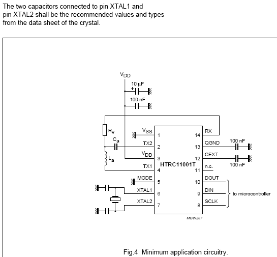
I can't figure out what these two capacitors by the crystal should be. I've read the data sheet for the crystal from top to bottom and it says nothing to this effect.

I've read up on crystals and learned their history, design and production. This was all very interesting but hasn't helped me with the actual question: What kind of capacitors do I need?

For reference, here is the white-paper for the RFID chip:
https://www.nxp.com/acrobat_download/datasheets/HTRC11001T_2.pdf
 

Attachments

  • rfid-crystal.PNG
    rfid-crystal.PNG
    19.1 KB · Views: 1,954
Last edited:
The component in the red circle is a crystal, and the component in the blue circle would probably be a tantalum capacitor. The 100nF caps depicted to the far right would probably be ceramic caps. Hope I've answered your questions!
 

Attachments

  • RFIDCrystalOscillatorHelp.JPG
    RFIDCrystalOscillatorHelp.JPG
    32.8 KB · Views: 139
Last edited:
The crystal datasheet will specify a load capacitance. That load is split between the 2 capacitors in parallel. Capacitors in parallel work like resistors in parallel. Typical values might be in the 12-30pf range. They help to guarantee that the oscillator will start up reliably.
 
Last edited:
Capacitors in parallel work like resistors in parallel.

No they don't. When resistors are in parallel you have to do the following:

1/R1 + 1/R2 + 1/R3... and so on. Then you find the reciprocal of that.

On the other hand, capacitors can be added when they are parallel and when they are in series you do the equation above. How do capacitors in parallel work like resistors in parallel?
 
I'm attempting to build the circuit in this RFID chip's white-paper. ...
I can't figure out what these two capacitors by the crystal should be. ...estio What kind of capacitors do I need?

**broken link removed** It gives the equations on how to select the crystals. Or, just try two capacitors in the 35pF range...
 
No they don't. When resistors are in parallel you have to do the following:

1/R1 + 1/R2 + 1/R3... and so on. Then you find the reciprocal of that.

On the other hand, capacitors can be added when they are parallel and when they are in series you do the equation above. How do capacitors in parallel work like resistors in parallel?
The two capacitors are in parallel with the crystal. They are in series with each other.
 
**broken link removed** It gives the equations on how to select the crystals. Or, just try two capacitors in the 35pF range...

I have tried very hard to read this article but it is just gibberish to me. Can you think of an article written in a more neutral tone?

I've searched Wikipedia for an article on the same matter and found this:
Pierce oscillator - Wikipedia, the free encyclopedia

This I can comprehend much easier however I am having difficulty applying this document to the RFID document because their crystal circuits are different. Any guidance in this matter is appreciated -- especially a simplified explanation of what it is I need to go and learn (or maybe a link to that article!).

**broken link removed**
rfid-crystal-png.33164


Given this:
The total capacitance seen from the crystal looking into the rest of the circuit is called the "load capacitance". When a manufacturer makes a "parallel" crystal, a technician uses a Pierce oscillator with a particular load capacitance (often 18 or 20 pF) while trimming the crystal to oscillate at exactly the frequency written on its package.
To get the same frequency performance, one must then make sure that the capacitances in the circuit match this value specified in the crystal's data sheet. Load capacitance CL can be calculated from the series combination of C1 and C2
I get this formula:
1/20 = 1/x + 1/x (20 is the crystal capacitance)
Doing the math you get
x/20 = 2
x = 40

So I need two 40pf caps? This seems rather large...
 
Last edited:
No they don't. When resistors are in parallel you have to do the following:

1/R1 + 1/R2 + 1/R3... and so on. Then you find the reciprocal of that.

On the other hand, capacitors can be added when they are parallel and when they are in series you do the equation above. How do capacitors in parallel work like resistors in parallel?

Have you seen a parallel resistor in any of the schematics? :confused::confused:
 
Status
Not open for further replies.

Latest threads

New Articles From Microcontroller Tips

Back
Top