Whiz? Are you still working on this circuit (in the meantime)?
I think I can see what you're trying to do. The series resistors were a good idea, they prevent the transistors blowing up too easily. I take it U1 is amplifying OK-ish?
I think an empirical approach helps. This is what I do with this kind of circuit.
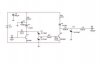
U2 is just not biased right at all, it'll probably run hot too. You need to have a at least a low value resistor between U2's E & B. Start with 47 Ohm.
Temporarily link out L3 and disconnect L4 from U2 C. The resistor R3 wants to be this 'broad-band dummy load' the conversation was about earlier. You definately can't use a bulb here (not unless working with a lower frequency).
Move trimmer C4 to across U2's e-b resistor. It's your choice whether you want to use 'L', or 'Pi' matching. Pi is more versatile. There needs to be a little bit more work here. In meantime for inspiration look at the example schematic that was posted earlier.
And roughly tune C3, C4 for maximum supply current (being dissipated in the 22ohm). This is the start of the empirical stage, the experience you get here is golden. You'll find the routine here almost identical to those Agilent Java 'tuning' applets I posted.
You might might find that one of both trimmers run out of travel, you'll have to suss out that one yourself. You're allowed to 'adjust' L1. It doesn't have to be 180.00 nH and it won't work any better either being exactly that value. But the adjustment of L1C3C4 is critical.
Remove link from L3, reconnect L4. Now you work further along the circuit, doing the same routine with the adjustments.

 I guess I'll have to assume it's 550 ohms resistive.
") Until now, I claimed I could find anything.
Until now, I claimed I could find anything.  S-parameters are only given down to 150, OP is designing for 100. I guess that's DC on this data sheet.