Continue to Site

Welcome to our site!

Electro Tech is an online community (with over 170,000 members) who enjoy talking about and building electronic circuits, projects and gadgets. To participate you need to register. Registration is free. Click here to register now.

  • Welcome to our site! Electro Tech is an online community (with over 170,000 members) who enjoy talking about and building electronic circuits, projects and gadgets. To participate you need to register. Registration is free. Click here to register now.

RF signal amplification

Status
Not open for further replies.
What load is the transmitter going to drive?

a simple dipole.. i'll DIY it... maybe i'll use a hanger


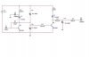
i think it might get you enough drive for the 2N3866

great! i'm proud that i managed to find a usable transistor... the luck of the newbie :D but probably the output of the 2N3866 will be less than 1W right?

i also intent to use VK200 for filtering where i think it's needed.
 
It's essential that you use only non-inductive resistors.

These 'never' things often get too serious...

When I didn't have any alternative I'd used 2 green vitreous enamel 100R wire-wound resistors in parallel easily, no problem for 30 watts. All I had to do was insert a variable capacitor in series and tune it to null out the inductance, it worked fine, the resistors don't mind being run red-hot. Across the resistor you can place a small 24 V light bulb as well that glimmers rather than blinds you. Not rocket science! For big watts, in a hurry I'd even put it in a jug of water and added more water if it boils away, but you have to be desperate to resort to that.

Light bulbs (of the appropriate ohmage) are fine for dummy loads, you can add a capacitor there too to null inductance out.

A SWR meter is a useful tool. I ha a CB radio one which worked fine for 100 MHz band. A dummy load is theorectically supposed to be 1:1 reading. This "1:1 SWR thing" you hear I think is taken too seriously by radio people, 2:1 SWR is fine in practice, there's hardly any difference at the recieving end.
 
Last edited:
The problem with using an inductive load is that now you complicate matters. It is much easier for the hobbyist, with his limited RF test gear, to try and tune his amplifier into a purely resistive load rather than into a very reactive one.
VSWR is important if you want max range out of your transmitter. Yes, 2:1 is OK, but I'd call that the limit especially with an under built amplifier with no VSWR protection circuitry built in.
 
These 'never' things often get too serious...

When I didn't have any alternative I'd used 2 green vitreous enamel 100R wire-wound resistors in parallel easily, no problem for 30 watts. All I had to do was insert a variable capacitor in series and tune it to null out the inductance, it worked fine, the resistors don't mind being run red-hot. Across the resistor you can place a small 24 V light bulb as well that glimmers rather than blinds you. Not rocket science! For big watts, in a hurry I'd even put it in a jug of water and added more water if it boils away, but you have to be desperate to resort to that.

Wirewound resistors won't be anything like 50 ohms at 100MHz, so completely pointless using them. Also, don't dump them in water, dump them in oil for cooling.

Light bulbs (of the appropriate ohmage) are fine for dummy loads, you can add a capacitor there too to null inductance out.

You can't use a completely inductive load at VHF, nor can you 'null it out' with a capacitor.

Light bulbs are reasonably 'OK' but only at low frequencies.

A SWR meter is a useful tool. I ha a CB radio one which worked fine for 100 MHz band. A dummy load is theorectically supposed to be 1:1 reading. This "1:1 SWR thing" you hear I think is taken too seriously by radio people, 2:1 SWR is fine in practice, there's hardly any difference at the recieving end.

There's a hell of a lot of difference, your radiated power is much less, and (more importantly) the lost power is been reflected back to the transmitter, causing it to run much hotter and potentially fail.

You'll never get 1:1 in to an aerial, but it's 'as good as' into a dummy load, which is why it's essential such a load is non-inductive and an accurate value.
 
If a "wirewound resisitor is no good", why does my SWR meter say that this load is very nearly 1:1 ?

I know the SWR meter works correctly, because different value resistors I try shows the exact correct increase in SWR.

This is only 100 MHz, it's not microwave you know!

And in any case if you have an ATU, you can easily use a pair of curling tongs as a dummy load at 1:1 SWR. Yes I have tried it.

Well of course a non-inductive resistor is preferred, I am saying for a narrow range of frequency and if you're desparate for a large power, wirewound works fine with a capacitor.
 
2:1 SWR is fine in practice, there's hardly any difference at the recieving end.

I don't get why you say that. 2:1 VSWR is like a 25% reduction in power if I recall correctly.
 
If a "wirewound resisitor is no good", why does my SWR meter say that this load is very nearly 1:1 ?

You're not a radio amateur eare you?, and never have been.

I know the SWR meter works correctly, because different value resistors I try shows the exact correct increase in SWR.

This is only 100 MHz, it's not microwave you know!

No, but it is VHF, and a piece of stright wire can be all you need for a tuned inductor at these frequencies - wirewound resistors are massive value inductors at 100MHz.

And in any case if you have an ATU, you can easily use a pair of curling tongs as a dummy load at 1:1 SWR. Yes I have tried it.

Well of course a non-inductive resistor is preferred, I am saying for a narrow range of frequency and if you're desparate for a large power, wirewound works fine with a capacitor.

As a non-radio ham you obviously have no idea what a dummy load is, and what it's used for - essentially it's a known fixed value, you can't use a dummy load that only works at one frequency and has to be adjusted to make it work at all.
 
Wirewound resistors won't be anything like 50 ohms at 100MHz, so completely pointless using them. Also, don't dump them in water, dump them in oil for cooling.
....

Even carbon film ones are said to show inductive behavior. Best appear to be carbon composition type. MFRs are used in RF circuits( perhaps may not be as dummy loads.
 
If a "wirewound resisitor is no good", why does my SWR meter say that this load is very nearly 1:1 ?

I know the SWR meter works correctly, because different value resistors I try shows the exact correct increase in SWR.

This is only 100 MHz, it's not microwave you know!

Marc, Marc, Marc. I am losing faith in you, wirewound resistors at 100 Mhz?

Surely your load was used at a very low frequency. At a 100 Mhz my farts will detune a load let alone a 5 inch coil of wire.

I forgot to check how many watts we were talking about...
 
This is only 100 MHz, it's not microwave you know!

sure it's not microwave, but using the inductance of a typical "noninductive" wirewound resistor, 1.5uH, XL at 100Mhz is 942.4 ohms, far from a 50 ohm match. even the best "noninductive" resistors have a parasitic inductance of 0.2uH for an XL of 125.6 ohms, which is still out of the ballpark for anything better than a 3:1 match.
 
At a 100 Mhz my farts will detune a load let alone a 5 inch coil of wire.
:eek:

Mike I am becoming very worried about your digestive system.
You should re-evaluate your diet on an urgent basis.:D


Lamps as a dummy load?
Bad idea, the resistance changes with brightness.
They dont exactly follow Ohms law... OOPS DONT GO THERE:p

JimB
 
For VHF you need to use think film resistors which can work into the microwave bands.
 
thanks people! marcbarker thanks alot for your interest
on my lil projects :)

i'll come back on that as soon as i have a finished design so we can
comment it and correct any possible errors before building it.
 
update...

so here's my design... kchriste's link helped alot!
 

Attachments

  • RFamp.jpg
    RFamp.jpg
    20.3 KB · Views: 334
Last edited:
That's a but harsh Nigel, go easy on the nube!

C4 and C3 are effectively in parallel with each other giving you 20pF to 60pF; are you aware of that?

Have you tried simulating it?
 
C4 and C3 are effectively in parallel with each other giving you 20pF to 60pF; are you aware of that?

Have you tried simulating it?

using the caps and the coil i'm trying to fix the impedance between stages..

i haven't simulated it never managed to do a decent simulation on multisim...usually i do the circuit and then connect the instrument and i don't get any reading...

also on LTspice many components are missing.. so i couldn't simulate it...
what's wrong with my circuit?
 
Status
Not open for further replies.

Latest threads

New Articles From Microcontroller Tips

Back
Top