Continue to Site

Welcome to our site!

Electro Tech is an online community (with over 170,000 members) who enjoy talking about and building electronic circuits, projects and gadgets. To participate you need to register. Registration is free. Click here to register now.

  • Welcome to our site! Electro Tech is an online community (with over 170,000 members) who enjoy talking about and building electronic circuits, projects and gadgets. To participate you need to register. Registration is free. Click here to register now.

restoring old valve radio

Status
Not open for further replies.

sillypig

New Member
hi all I'm restoring an old valve radio
i have got hold of the schematic of it but just to make sure i want to replace all the resistors
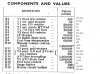
i have put a photo of the original resistor list just want some one to check see if i have them correct
thanks
marko
 

Attachments

  • valve resistors.jpg
    valve resistors.jpg
    209.4 KB · Views: 335
Something I notice from that list, many of the values are not modern "preferred values", so it may be necessary to substitute the nearest preferred value.

Before embarking on a wholesale replacement, it is well worth checking the values of the existing resistors.

My best guess is that lower value resistors (less than 1k Ohm) will be well within tolerance (+/- 20%),
higher value resistors (greater than 10k Ohm) will have drifted high in value),
wirewound resistors will either be the same value as the day they were made, or have gone open circuit.

JimB
 
The resistors are probably OK. I would worry about the capacitors first, and most of them are OK.
 
hi guys i'm just going to replace the caps first and power her up and see what happens fingers crossed.
 
The only real troublesome ones are the bumblebee caps and the electrolytics. Be careful what you change in the tuned circuits.

The service manuals usually have resistances that can be measured "in-circuit" from various points.

I don't know how old the radio is, but watch out for resistance line cords. They had Resistance on purpose.

Variac's are always useful. Especially if you can monitor the voltages across the caps.

Here is an article of interest: https://www.vintage-radio.com/projects/capacitor-reformer.html

amd https://www.nmr.mgh.harvard.edu/~reese/electrolytics/
 
Last edited:
I h ave a small collection of valve sets.
resistors seldom cause problems, ones 100k and over can sometimes go high in value.
Power supply electrolytics are a problem and either go short or leaky (both electrically and the sticky goo).
Make a test jig that puts a 60w light bulb in series with the mains live for initial testing.
Also take care if the set has a plug in mains lead, these often do not have a polarising pin, and one way round the chassis will be live.
What set is it?
 
it is a pye mpu 40 bought for a fiver.
funny how so many tube radio's sell on ebay for £1 shame on them
 
Nice set and well worth 5 notes.
They had trouble with the valve bases, but they are well made sets.
Ebay brings up sets at a pound yes, but you have to think are they really worth more, this one is.
I often see some that are only worth a fiver for over 100 notes, because someone is being greedy.
 
There used to be a saying, the better the radio/amplifier, the more it weighs.

I do like the sound of a tube radio, but I rarely listen to the radio anymore except in the car. I just prefer quiet. In the car, the OFF button and volume control are always nearby.

I have a tube set that doesn't work anymore and a very pretty Magnavox console that is AM/SW. It works, but hums a little and has some issues with the dial cord. I got the optional FM tuner section as a carcass. No tubes or shields at all. There is even a tube radio on the porch.

As a kid I used to listen to the Voice of America Breakfast show on ShortWave. Somewhere in the house is a "portable" tube radio. Ya know, B batteries? I think it used 22.5/45 V and it had some tubes with a 1 V filament.

Very similar to this: **broken link removed** but looks more like this:

Link: https://www.google.com/search?site=...90%2Fantique-wood-magnavox-1950s-late;300;225

What's very add, is that only the right door opens and the hinge side is in the middle of the cabinet. No handles, per se. The door extends a bit on the right and there is no wear on the side of the cabinet either.
 
Consoles were not as popular as tabletops, people that owned their own house tended to have them, I spose a lot of people rented way back.
And because of the space they take up are still not all that popular, but there are some examples worth a lot of cash.
Unusal for a fm tuner head not to have valves, theres usually one or two ecc82/3's, as the pre amp/frequency changer. the resultant 10 mc's if being injected into the first or second stage if on what was the am side of the set, with a load of switch contacts changing the frequencies from mf to vhf, or switching transformers, the contacts frequently causing trouble at vhf.

If your set hums then smoothing caps are a obvious cause, or if its an older set there is a hum balance choke either on the chassis or part of the speaker magnetising coil (really old sets have an electromagnetic speaker), these often have taps you can select, or on posh sets theres sometimes a wirewound pot.
 
Yep, the electromagnetic speaker and your right, the filter caps which mean rebulding the cans.

Ultimate plans are to add this regulator: https://glass-ware.stores.yahoo.net/ps3.html

I'm also collecting test equipment. e.g. AM/FM signal generator.

The main area has the selector for FM. It was optional and just like a separate FM tuner it would have it's own display. There were two versions of the FM tuner. One with the tubes inverted with respect to the dial, which this one needs and one non-inverted. I have a solid state tuner connected to it now.

Way back when, my father replaced the 78 turntable with a "more modern" one. He then put a small tube amp for the console to play stereo. At the time, we hid the extra speaker in the console of the TV.

When I was, I would guess, maybe 10, I worked on tube radios and TV's and I respected 300+ volts. It did take me a while to have the courage to disconnect the high voltage anode lead. So, for part of science project, I needed to construct a 3 KV supply. Work, got me to work on a highly regulated 15 KV at 1.5 Amps, shunt regulated by a TUBE. Then there was the 100 kV at 0.1 A X-ray tube supply and the 1000 W RF transmitter. The 15 kV supply was always failing before I got involved, so I fixed it for good. The 100 kV supply was noisy, so I rebuilt that too. Then there was the stupid lamp that needed 40 kV to start and operated at 40 A and 22 V. The OEM manufacturer put in a 10 A rectifier and they got an earful from me and fixed/upgraded for free.
 
That will ceratinly increase sound quality, however value might well decrease, but if its quality you want good idea.
There has been some controversy whether regulating heaters actually does any good or not, I'll sit on the fence on that one.
I maintained an rf weld set where I used to work, it was part of a tube mill that made vehicle exhaust tube, that was basically a lw transmitter but without an aerial, the o/p went to a load coil to weld the tube seam, it was driven by a very large triode, and it too commanded respect as it ran at eht.
 
There is controversy about everything. We do know about the existence of "hum pots" in certain systems, so it would stand to reason that regulating the filament MIGHT help, however the filament is noting but a thermonic source of electrons, so AC ripple really should not matter.

That little regulator is also for the B+ which should have an impact on hum.

Where I worked, we rented an orbital welder, It made child's play out of welding VCR fittings on 1/4" stainless tube. Nearly anyone could do it.
 
Yea, fittings that are not in the mainstay. Good to 1000 F and ...: helium leak tested to a
maximum leak rate of 4 3 10 –9 std cm3/s with silver-plated and copper gaskets and to a maximum leak rate of 4 3 10 –11
std cm3/s with unplated gaskets." and for 1/4" pressure ratings around 5000 PSI.

https://www.google.com/url?sa=t&rct...opukDbG1oW1SDSQ&bvm=bv.68191837,d.cWc&cad=rja

VCO fittings use an O-ring seal.

https://edmonton.swagelok.com/blog/bid/325525/The-Advantages-of-Swagelok-VCR-and-VCO-Fittings

Not much info on orbital welding: https://www.swagelok.com/Columbiasc/Services/Orbital Welding.aspx


https://www.google.com/url?sa=t&rct...=2zuUZZK1V38FQaXUT7t6ig&bvm=bv.68191837,d.cWc

 
Status
Not open for further replies.

Latest threads

New Articles From Microcontroller Tips

Back
Top