Continue to Site

Welcome to our site!

Electro Tech is an online community (with over 170,000 members) who enjoy talking about and building electronic circuits, projects and gadgets. To participate you need to register. Registration is free. Click here to register now.

  • Welcome to our site! Electro Tech is an online community (with over 170,000 members) who enjoy talking about and building electronic circuits, projects and gadgets. To participate you need to register. Registration is free. Click here to register now.

Reset Problems

Status
Not open for further replies.

tml1220

New Member
I inherited a mess. I have a existing design in which the microprocessor is sometimes reseting. The original designer left the company in 1998. I have been at my current position for 1 year. We are seeing nuisance resets of the processor. The reset doesn't happen all of the time. It only happens 3 or 4 time a day. I have gotten some of the boards back that have the reset problem, but I can't get the processor to repeat the problem.

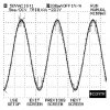
I know it has something to do with a power supply (Powering a low wattage light) in parallel with the transformer that supplies power voltage regulator then to the processor. I have no control over the Low Voltage Light's power supply because our parent company manufactures that devise (It plugs into our unit).

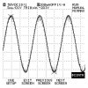
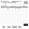
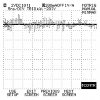
I have scoped out the MCLR line and I see VERY VERY fast Voltage spikes and Drops. These occur in less than 1ns. Processor runs at 4MHz.

I have tried an appropriate TVS with no help.

Any suggestions???

Some other bits of info:
PIC16C57
programmed for POR but NOT for BOR. I would think that if the processor would be programmed for BOR this would cause MORE resets......


T
 
For operating uCs in industrial environment, you have to be very careful with the power supply and PCB design. Check for the following thing on the PCB
1) Does all IC's have power supply decoupling capacitors near its supply pins? If not you got to put 0.01uF - 0.1uF caps. across the power pins.
2) The Vcc rail also rquires a ferrite bead / RF choke. This should be placed near the uC.
3) Does the PCB has ground plane/ copper poured areas? If not design new PCB with ground plane or copper pour.
4) Use a reset controller IC for your uC.
5) And finally, house the PCB in a metal case (Faraday Cage) to protect it from RFI/EMI.
 
unexpected resets

All good suggestions from kinjalgp. Is the reset line only used during power-up, or are there additional external trigger sources?

Unexpected pulses on the reset line, even those having very short durations, can reset the micro in the erratic way you mention. You should first try to determine whether the spikes are actually coming off the reset line or are being generated by power supply dips. Look at the positive supply with a scope, if you see the same type of short spikes that appear on the reset line, you have some larger power supply de-coupling issues to deal with.

If you determine the problem is on the reset line, either use #4 above, or try using a noise discriminator circuit (if there are additional external reset sources). The following circuit is from an old RCA CMOS manual. Input pulses having a duration greater than t1 produce an output pulse of duration t2, shorter input pulses are ignored. t1 = R1C1 and t2 = R2C2. The diodes speed up the recovery time of the circuit. Hope this helps. - CAL
 

Attachments

  • noise_filter.gif
    noise_filter.gif
    8.8 KB · Views: 593
Scope of circuit

I used an O-scope to record the Min-Max of the Vcc, MCLR(active low), and the AC @the input voltage. I turned on the switch on-off for 5 minutes. Here is what I got:
 

Attachments

  • BCVCC.jpg
    BCVCC.jpg
    63.3 KB · Views: 568
  • BCMCLR.jpg
    BCMCLR.jpg
    65.5 KB · Views: 573
  • BCSLAC.jpg
    BCSLAC.jpg
    66.5 KB · Views: 572
The MCLR line seems very noisy. Check that PCB track of MCLR line is not too long. It is advisable to use reset controller in such case.

Even Vcc is fluctuating noticeably. Use of good regulator along with RF choke is recommended.
 
Still have reset problems

I eliminated All of the spikes in Vcc and MCLR lines by adding a in-line filter (corcom 10eh1). The customer is still seeing the resets. So I know that was not the problem.

The problem happens when the operator turns on the light (the light has its own power supply) that is in parallel with our power supply. So in the initial state, (t=0) when the light switch is turned on, it resets our uC. So, I'm thinking there is an IN-rush of current to the lights power supply at t=0........


Another problem is I can't re-design because there is no design software in place to do a re-design(but it is in the budget for next year:) ). I'll have to try to compinsate by changing/adding components if I can. My hands are tied.


Tim
 
You need to do a transient analysis of the Vcc line when lights are turned. Use high speed DSO to see whats happening on Vcc/MCLR line on flipping the switch. May be the filter you connected is not able to arrest the spike generated by switching on the lights.
 
If the problem is negative spikes on the supply line, then isolate the micro with a series diode and cap on the supply. The cap will hold the voltage up when the diode turns off during the spike. If you cannot afford to lose the .6 volts of the diode and the supply is via a regulator, then jack up the bottom of the regulator with a diode to compensate.
 
Hi:

All the suggestions put forth have been excellent, and should be followed as part of a good robust design. Here is my take on it (a fast digital scope triggered when the light is turned on should prove or disprove it).

It could be that the big inrush current when the light is turned on is actually causing a voltage droop on the power line to the micro, and it is resetting due to this. Does it have a reset/supervisor circuit? Filament lamps have low initial (cold resistance). Also if the lamp supply is a switcher, it can have huge inrush currents depending on the state of the magnetics and the phase of the mains at the moment of turn on. You could try adding a big capacitor across the supply to the micro to absorb this droop.

Good luck,

Jem
 
Cap.

Jem,

That is what i was thinking in a Capacitor BUT i have another problem. It just so happens that this application is for use in a medical instrument (non-life support). Medical instruments/products have a patient leakage current requirement of no more than 300uA. Capacitors have high leakage current. The other problem is that I cannot repeat the problem here with the returned unit. It will only happen at the customers facility.


T
 
Can you give more details about in-line filter that you have used?

I would suggest you to have power supply like this. It solved same problem which I faced with one of my uC project. Let the line filter be there before the transformer and rectifier. It will have an added advantage.
 

Attachments

  • PS_181.gif
    PS_181.gif
    3.6 KB · Views: 479
Hi Guys,

One thing tickles me....... If tml1220 has this problem only at the customers site and not at his place, then surely there must be something wrong on the supply line at the customers place???
He has simulated everything at his place but no resets occur.........!!
Just as a test, try running the whole application through a cheap UPS.

Just an idea.........
 
Tml1220:

The capacitor you are referring to are generally across from Line to Gnd, and Neutral to gnd (I think they are called X capacitors. Can never remember which type is X, and which type is Y). The one I am proposing goes straight across the Vdd and Gnd of the micro. It is generally around 1000uF or so, with fairly low ESR.

Jem
 
Reseting uC

Hi all,
Fist off I want to thank you guys for all of the great suggestions and replies.

kinjalgp,
Here is the filter I used.

http://www.corcom.com/catalog/filters/H/Default.htm

It is an AC power filter. I have used filters/chockes in industrial machine tool applications where huge servo motors would apply power back to the power supply. This filter was readily avalible to me in house. After using the filter I recorded the readings below.


Chili, That was my thought too. I suggested that we use a an Isolation transformer but the salesmen and field service tech freaked out when I showed them what I wanted to use. lol It also might be a problem in the facility because sometimes medical facilities have x-ray machines in an adjacent room, running on the same power line. ???


jem, thanks for the suggestion. I'll look into it.


Another possible solution I have been thinking about is to increase the xfmr on the power supply. The only problem with that is I have to find a bigger xfmr with the same size footprint. This circuit board design has the xfmr onboard (30VA).


T
 

Attachments

  • ACWFilter.jpg
    ACWFilter.jpg
    53.9 KB · Views: 437
  • VCCWFilter.jpg
    VCCWFilter.jpg
    44.2 KB · Views: 432
  • MCLRWFilter.jpg
    MCLRWFilter.jpg
    46.7 KB · Views: 441
The Vcc and MCLR seems preety clear than before.
Can you show us your power supply schematic? It is adviasble to use large capacitor 1000uF after rectifier to maintain power to the circuit in case of large surges. See above given schematic for reference.
 
circuit

Here is the circuit. The light's power supply is powered by J2 pins 3 and 4.


T
 

Attachments

  • bccircuit.jpg
    bccircuit.jpg
    86.5 KB · Views: 210
I have a few suggestions
1) Change the decoupling capacitor near PIC from 0.001uF to 0.1uF
2) Datasheet of 7805 suggest use of 0.1uF between its output and ground terminals which is not shouwn in the schematic. Let the 10uF cap be there. Connect 0.1uF in parallel with it.
 
Status
Not open for further replies.

Latest threads

New Articles From Microcontroller Tips

Back
Top