Thursday August 19th 2021
Hi and thanks in advance to all for your time, knowledge and help.
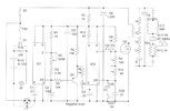
I found this circuit, it´s a variable signal generator that goes from 5KHz to 25KHz. The fuse is a 2 Amperes and the voltage 12VDC. The L1 must be wind with 24 gauge and is only 50 turns, the E cores where must be wind is a Hitachi 30.48 Inductor which does not appear in internet and for that reason the dimensions and material of which is made is unknown..
I built the circuit according to the diagram and as I could not find the specifications of L1
I end up making my own inductor with the help of software, one called Calculo de Bobinas and also miniRing Core Calculator.
The inductor I made is:
Air core one layer
Core diameter 70mm no space between turns.
29 gauge wire
116 turns
8 Ohms of resistance
I made it that way so the current is in the range of the fuse (2 Amps). 12vDC/8 Ohms =1.5 Amps.
The circuit never sounded, it did not work until I made the modification that appears in the second diagram.
This one is the original diagram.

This is the modification.
With this modification the piezo tweeter produced sound but the volumen is really low not the powerfull sound that I expected, (of course this in the audible range).

There are some things, some connections that I suspect are not correct but I am not an expert even though I see no reason to join the pin 3 with pin 8 of the 555 timers.
Should the connection of Q1(a PNP transistor) to pin 5 of IC2 be in the lower part of the transistor which is the collector?
This diagram shows what I think is not correct.

I also made this modification but there was no improvement neither decrease in the volumen. (The volumen remains the same)

These are the E Cores of the Hitachi 30.48 Inductor that I could not find.

I haven´t change the timers, maybe they were damaged because of the 3 to 8 pin connection.
The question.
How can I make it louder?
Hi and thanks in advance to all for your time, knowledge and help.
I found this circuit, it´s a variable signal generator that goes from 5KHz to 25KHz. The fuse is a 2 Amperes and the voltage 12VDC. The L1 must be wind with 24 gauge and is only 50 turns, the E cores where must be wind is a Hitachi 30.48 Inductor which does not appear in internet and for that reason the dimensions and material of which is made is unknown..
I built the circuit according to the diagram and as I could not find the specifications of L1
I end up making my own inductor with the help of software, one called Calculo de Bobinas and also miniRing Core Calculator.
The inductor I made is:
Air core one layer
Core diameter 70mm no space between turns.
29 gauge wire
116 turns
8 Ohms of resistance
I made it that way so the current is in the range of the fuse (2 Amps). 12vDC/8 Ohms =1.5 Amps.
The circuit never sounded, it did not work until I made the modification that appears in the second diagram.
This one is the original diagram.
This is the modification.
With this modification the piezo tweeter produced sound but the volumen is really low not the powerfull sound that I expected, (of course this in the audible range).
There are some things, some connections that I suspect are not correct but I am not an expert even though I see no reason to join the pin 3 with pin 8 of the 555 timers.
Should the connection of Q1(a PNP transistor) to pin 5 of IC2 be in the lower part of the transistor which is the collector?
This diagram shows what I think is not correct.
I also made this modification but there was no improvement neither decrease in the volumen. (The volumen remains the same)
These are the E Cores of the Hitachi 30.48 Inductor that I could not find.
I haven´t change the timers, maybe they were damaged because of the 3 to 8 pin connection.
The question.
How can I make it louder?