Continue to Site

Welcome to our site!

Electro Tech is an online community (with over 170,000 members) who enjoy talking about and building electronic circuits, projects and gadgets. To participate you need to register. Registration is free. Click here to register now.

  • Welcome to our site! Electro Tech is an online community (with over 170,000 members) who enjoy talking about and building electronic circuits, projects and gadgets. To participate you need to register. Registration is free. Click here to register now.

Remote Timer Reset Black Box

Status
Not open for further replies.

kadini

New Member
I am trying to set up a device that will automatically push the reset button on a separate streaming device every 48-72 hours. I tried just cycling the power on the device but that doesn't work. Pushing the reset button has been 100% reliable.

So, what I have come up with is
1. Use a simple light wall timer commonly available at Home Depot, Lowes or online for $10-$15.
2. The timer plugs into a wall plug and is set to turn on power to a 120v AC to 12V DC power supply, also commonly available
3. Then the power supply energizes a 12V solenoid which pushes the reset button.

I don't have the mount for the solenoid and how to attach it the streaming device 100% worked out but I am confident there's a simple solution, have some ideas.

The real problem I have is the minimum power on increment available using the timer is one minute. I only need the solenoid energized for 1-2 seconds. If it pushes the reset button for longer than that (I think it's 30 seconds) it could have undesired effects like resetting the streaming device to factory defaults. Also concerned with overheating the solenoid if it's on for too long.

One potential solution is to use this timer switch http://timers.shop/6V-28V-10-Amp-Timer-POSITIVE-OUTPUT_p_13.html which can be programmed to energize the solenoid for 1-2 seconds.

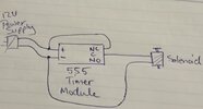
This is all shown schematically in the attached .pdf. The part numbers for the 12V power supply and solenoid came from a website where I found lots of good stuff. But when I asked for help and recommendations they told me to buzz off. One concern I have is that the 12V power supply is compatible with the solenoid.

So, this is really not a circuit but rather a combination of off the shelf devices I'm trying to cobble together to make a reset device. I would like for all the components to be UL listed. I found some hobbyist solenoids out there that would probably work but they look pretty iffy. Also would prefer not do do any soldering if possible.

Hope this is clear.

Any help you can offer is appreciated.

Thanks.
 

Attachments

  • Reset Black Box Rev B.pdf
    67.4 KB · Views: 249
You can make the solenoid so that it actuates only on the rising edge of the output of the DC power supply with just a series capacitor. But we need to know the minimum time to be held and the resistance spec of the solenoid.

I'm assuming that the DC power supply is a switchmode supply.
 
Your plan looks good.

ebay has a zillion timer modules. The most basic are under $3 for a 555 circuit with a relay output, adjustable for 0-10 seconds. Here is one without the China delay.


ak
 
So far all I have is the plug into the wall light timer switch.

I don't have the
120V AC to the 12V DC power supply
The 12V Solenoid
Or the delay switch

I can buy any of the above 3 that are recommended. In fact, I was really hoping to get recommendations.

I don't know what a switchmode power supply is. I even looked it up and still am not sure what it means. If a capacitor can replace the pulse timer (or timer delay) switch that's great. Which one would work with what power supply and what solenoid? (The power supply should plug into the wall timer, just like it was plugging into a wall outlet.)

The force required to push the reset button is small BTW, probably an ounce would do it.

The NE555 timer delay relay seems to delay the time between when the power supply is energized and the solenoid gets energized. Don't think this is what I need? I need a relay, or whatever, that energizes the solenoid for 1-2 seconds, and then won't energize the solenoid again until the power is cycled again. Can the NE555 timer do that?

Always happy to buy American when possible!

If I'm missing something please forgive me. This is not one of my areas of expertise.

Thanks.
 
I don't know what a switchmode power supply is. I even looked it up and still am not sure what it means. If a capacitor can replace the pulse timer (or timer delay) switch that's great. Which one would work with what power supply and what solenoid? (The power supply should plug into the wall timer, just like it was plugging into a wall outlet.)
The modern power supplies are mostly switch-mode; you can usually tell because they weigh much less than the older transformer-based power supplies. The switch-mode supplies have a regulated output voltage.
The NE555 timer delay relay seems to delay the time between when the power supply is energized and the solenoid gets energized. Don't think this is what I need? I need a relay, or whatever, that energizes the solenoid for 1-2 seconds, and then won't energize the solenoid again until the power is cycled again. Can the NE555 timer do that?
That relay has 3 contacts: normally-open (NO), normally-closed (NC), and common (C). The NC and C contacts will be connected together when you power it on, and disconnected after the programmed time (i.e. 2 seconds). The connection between the NO and C contacts will be opposite that.
 
I tried to find a manual or instruction sheet for the NE555 but no luck.

Is it possible you could draw me a schematic on how the wires should connect and how to set the time interval?

Also will it work with this solenoid


and this power supply (I guess i can remove the plug and just use the wires)


I think both the solenoid and power supply may be overkill (and expensive) but I want devices that are UL listed.

And, sorry for the McMaster-Carr logos, but this is the only place I could find that seemed have what I needed. (I asked them for help too and they were less than helpful, to put it politely.)

Again, if there are better options out there I am all ears.

Thanks.
 
Here's the wiring diagram. Preferably there would be a diode or snubber on the solenoid to stop arcs on the relay contacts.

The time interval is set by rotating the little screw on the blue component
 

Attachments

  • IMG_20211030_174040.jpg
    IMG_20211030_174040.jpg
    328.4 KB · Views: 236
1st off, thanks a ton for all the help!

And, again, please forgive my ignorance.

OMG!??! Diode? Snubber? Sounds like some soldering?

OK, I have done some limited soldering. Just not enough to ever get good at it.

So where in the diagram above would the snubber go? Which diode should I use as a snubber?

Might it also be a good idea to add a fuse to the mix?

Also, again, any reason to think this power supply and solenoid combination


won't work with all of the above?
 
The supply is fine. The solenoid is ridiculously expensive, but should work fine. Here are alternatives.


Any website into robotics should have an assortment of solenoids.

ak
 
I am trying to set up a device that will automatically push the reset button on a separate streaming device every 48-72 hours. I tried just cycling the power on the device but that doesn't work. Pushing the reset button has been 100% reliable.

So, what I have come up with is
1. Use a simple light wall timer commonly available at Home Depot, Lowes or online for $10-$15.
2. The timer plugs into a wall plug and is set to turn on power to a 120v AC to 12V DC power supply, also commonly available
3. Then the power supply energizes a 12V solenoid which pushes the reset button.
Your plan is good if you want an inexpensive workable solution.
Otherwise, there are single timer devices that will provide the required timing functions, operate at 120VAC. and UL certified.
They are expensive ($280 USD :eek:) but purpose designed. You could buy a small PLD for alot less than that.;)

What is needed is a programmable 24hr Time switch with pulse output. This device allows programming of the hourly/daily switching interval as well as the output pulse duration.

Example timer device:


You would still need a 12VDC wall wart, 12v solenoid, and a way to attach the solenoid to the streaming device.

I don't have the mount for the solenoid and how to attach it the streaming device 100% worked out but I am confident there's a simple solution, have some ideas.
What is the name and model number for the streaming device?
 
What is the name and model number for the streaming device?
It's a Tablo Quad with built in hard drive.

If we upgraded the router, got rid of the UPNP, and set DHCP and port forwarding that would fix the problem. Too much resistance in the household to implement that. (Even though it would be better in almost every way imaginable, and have better secutiry. I'm not bitter...)

Or if Tablo would give a remote reset option in their firmware that would help, as long a you remember to do it before it goes offline.

I am not worried about mounting the solenoid so it can push the Tablo reset button. It's not a difficult problem. Once I have the solenoid in hand I'll figure out a way to attach it to the board that the Tablo will be attached to (already figured that out).

I promise, once it's all set up I'll post a picture.

I do appreciate all the help. But I'm not going to spend $280.

I have a $12 plug in wall timer.
I have a delay switch.
I have options for power supply and solenoid.

Questions:
1. Do I really need the diode (snubber) to stop arcing at the relay contacts? Is that really a serious problem, like as in fire hazard?
2. If I do need the diode which one should I get and where does it go in the circuit diagram above?
3. Any comments on the virtues of adding a fuse? How failsafe is this? If the delay switch fails it just stops working, no melt downs or anything scary like that?

I just don't want to set the house on fire.

Thanks again for all the wonderful inputs.
 
Can you arrange the solenoid so it activates a cam that momentarily presses the reset button? It will probably press it again when released but I assume that's fine.

Mike.
 
I suppose that possible. But I was planning to just have the solenoid directly push on the reset button. Again, once I have the solenoid in hand it'll be possible to figure it out.

The inout for the antenna coax cable is right next to the reset button so it's possible I may have to move the solenoid out a ways for clearance. But even in that case I think I could just attach an extension to the end of the solenoid shaft and still have everything linear and on the same axis.
 
OK, got everything together and wired up. Tried a test fire of the solenoid and nothing.

I checked all my connections (using screw posts, nuts and washers) with volt ohm meter and didn't find anything obviously wrong. Feel confident I hooked the wiring up correctly irrespective of the quality of the connections.

The 555 unit lights up in different ways when the power is applied. There are 2 different lights. Sometimes one or the other lights up (briefly), sometimes they both light up, sometime neither lights up.

Finally I disconnected the power supply from the circuit and hooked it up directly to the solenoid. And, nothing. Actually the solenoid did fire two or three times but couldn't make it work more than that.

I checked the continuity across the solenoid and it appears to be good.

So, is it possible my power supply doesn't have the amps it needs?
Is 25 gauge solid wire large enough for this application?
Is it possible it's just a bad solenoid?
And, assuming I figure it out how do you set the timer interval on the 555 unit. I see the litlle turn screw but don't know which way is more or less time, and even if I did don't know how far to turn it. Is it just trial and error?

1637805661087.png

Any help is appreciated.

Thanks.
 
It's possible the power supply isn't up to the task. If you can get access to a better supply, you can try the solenoid with that.

In the meantime, disconnect the solenoid, and see if the timer does what you want. The LEDs presumably illuminate to indicate what the relay is doing, so setting the time should be straight forward. It's possible that the solenoid was interfering with the supply, and consequently upsetting the timer.
 
The solenoid is 12 v dc push which is supposed to draw 2.5 Watts of power.

The power supply converts wall current, 120 v ac, to 12 v dc and says it's rated for 0.7 amps output.

Does this not equate to 8.4 watts from the power supply?

One other bit of info when i check the continuity across the solenoid it gives a return of 56.4 ohms.

So if the above power supply is not adequate, or otherwise incorrect, what rating power supply do I need?
 
You are correct, and at 56.4 ohms, it won't draw more than 2.5w. you also said that the power supply won't drive the solenoid, so either the supply is broken, or the connector is not making good contact. Or the diode is broken or connected backwards. The solenoid should be fine if it's still reading 56 ohms

Did you see what happens when the solenoid is out of circuit?

Is the diode pointing in the correct direction? Testing the diode with the multimeter might be worthwhile
 
For reference here is an example where a servo was used coupled with a
ESP8266 to detect presence/absence of a network in operation. If network
not "up" prwesses button on a hotspot to get it to reset/reboot.

Shows what can be done with GUI programming and simple low cost parts.
For future projects.....


Regards, Dana.
 
Status
Not open for further replies.

Latest threads

New Articles From Microcontroller Tips

Back
Top