OK........... I admit I have only simple knowledge about electronics but would very much appreciate any and all ideas on how to add a reset button to a circuit that I just purchased.
By reset, I would like to reset the 2 LED's both to a "0" each.
(Not reset the power.)
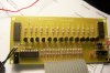
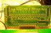
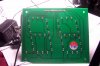
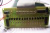
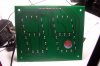
The circuit involved is an ALL ELECTRONICS Corp. LED 2-Digit Counter Kit.
I knew in advance that the circuit was not built with a "reset" included, but in my infinite wisdom (smile), I assumed I could reset the power and then the counters would return to "0". So much for infinite widom.............
In any case I have added attachments of this circuit in case somebody would recognize this IC, have pity on me, and have some idea on how to advise me on how to make a reset button. "I am capable of some soldering."
REMEMBER....I'm very limited in electronics knowledge so a nice "Electronics for Dummies" explanation would be very much appreciated.
The 3 chip numbers are 2@ - HCF4033BE
1@ - CD40106BCN
Once again thank you for your time and experience.
Sincerely Grateful and inexperienced
Sam
[email protected]
By reset, I would like to reset the 2 LED's both to a "0" each.
(Not reset the power.)
The circuit involved is an ALL ELECTRONICS Corp. LED 2-Digit Counter Kit.
I knew in advance that the circuit was not built with a "reset" included, but in my infinite wisdom (smile), I assumed I could reset the power and then the counters would return to "0". So much for infinite widom.............
In any case I have added attachments of this circuit in case somebody would recognize this IC, have pity on me, and have some idea on how to advise me on how to make a reset button. "I am capable of some soldering."
REMEMBER....I'm very limited in electronics knowledge so a nice "Electronics for Dummies" explanation would be very much appreciated.
The 3 chip numbers are 2@ - HCF4033BE
1@ - CD40106BCN
Once again thank you for your time and experience.
Sincerely Grateful and inexperienced
Sam
[email protected]
Attachments
Last edited:
")

