Continue to Site

Welcome to our site!

Electro Tech is an online community (with over 170,000 members) who enjoy talking about and building electronic circuits, projects and gadgets. To participate you need to register. Registration is free. Click here to register now.

  • Welcome to our site! Electro Tech is an online community (with over 170,000 members) who enjoy talking about and building electronic circuits, projects and gadgets. To participate you need to register. Registration is free. Click here to register now.

Reset Circuit

Status
Not open for further replies.

ksaomar1

New Member
Hi there

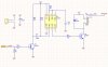
I would like to use the reset circuit you see in the attachment in a system that can reset the whole system by disconnecting the +12V from the InputVoltage for two seconds and then connecting the +12V to the InputVoltage again. InputVoltage supplies the system and +12V supplies only the reset circuit. The reset signal (when it is high) comes from the system itself.

I have this design but for some reason it woks for some boards and not to all boards, Do you think it is a problem in the design?


Regards,

Omar
 

Attachments

  • Reset.jpg
    Reset.jpg
    56.3 KB · Views: 182
Are you really leaving pins 4 and 5 not connected?
 
555 timer circuits have been notorious unstable. At one point, I did design a circuit for automotive use that would implement about a 0-4 second delay. The parts are hard to come by, but I might be able to build a few if coaxed. One of the biggest issues was reliable resetting, just as you have. I solved it, but it doesn't work for the 555. The triggering is mostly edges from differentiators.

My circuit would reset every time if a) the timeout passed or (b) The input V went below about 4 to 6V (c) Initial power up from being off for a long time.
It was basically a delay on make timer with a protected bipolar transistor output on the high side. Commercial power on reset circuits need basically 100-150 mS to reset. I easily was able to meet less than 10 mS. but it was difficult to measure.
 
Pin 5 should have a small capacitor to ground for noise. (.01ufd.)
 
A 100nF decoupling cap directly across the 555 supply pins might help, too.
Relay contact bounce lasting several mS will cause jitter on InputVoltage at power-up. Could that be a problem? Have you considered using a FET instead of a relay to switch InputVoltage?
 
Thank you so much guys for your help, I think I will redesign it, high in pin 4 and a small capacitor to ground in pin 5.

I am not planning to use FET for now, but I might use it if the problem continued.

I am sure this will help thank you so much guys for the amazing support.
 
Status
Not open for further replies.

Latest threads

Back
Top