Continue to Site

Welcome to our site!

Electro Tech is an online community (with over 170,000 members) who enjoy talking about and building electronic circuits, projects and gadgets. To participate you need to register. Registration is free. Click here to register now.

  • Welcome to our site! Electro Tech is an online community (with over 170,000 members) who enjoy talking about and building electronic circuits, projects and gadgets. To participate you need to register. Registration is free. Click here to register now.

Replacing vehicle alternator warning lamp with LED

Status
Not open for further replies.

CarlosFandango

New Member
I'm sure that this must have been done numerous times in the past, but I'm darned if I can find any definitive description of how to do it anywhere. As the title suggests, I'm trying to figure out how to replace an alternator warning lamp with an LED. There are a couple of issues it seems: many (most?) alternators require a field current of some apparently indeterminate value in order to work. I believe this is around an amp, but it may be more. Secondly, the voltage difference can be in either direction - [alt high + batt low = battery fault] or [batt high + alt low = alternator fault].

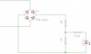
So, giving this some consideration: I'm thinking that the alternator warning lamp itself could be replaced with a power resistor, about ten ohms or so, to supply the field current; a bridge rectifier placed across this resistor could maybe feed an led. But apart from that I'm a bit stumped. I'm on the verge of some practical experimentation... but I've only got one alternator, and my truck needs it!

So does anyone have any pointers to how this might be done, or even better, some actual bona-fide practical experience? I'd be very happy to hear it if you have!

-CF
 
The field current bypasses the light, so you shouldn't need the power resistor. When the alternator fails, the isolation diodes can't keep the field at a voltage higher than the battery - so at that point the current runs from the battery runs through the light to the field windings, yes.

But when that happens, it doesn't matter, because the alternator is dead anyway.

So add a 560Ω current limiting resistor on the anode of the LED, so these two components are in series. Place a 1N4004 diode backwards across the led to protect it from the reverse voltages - these two components are in parallel. This circuit will replace the light.

Tricky part is determining which way to put it in - it won't work backwards. Take the old light out. Switch on the ignition without starting (not "acc", but "on"). Measure in the lamp socket to ground on each side. One side will be +12V, the other near 0V. The resistor hooks to the +12V, the cathode of the LED (and anode of the 1N4004) hooks to 0V.

To test it, take the belt off so the alternator doesn't turn when you start it. Start it, verify the light came on, measure about +12V on the battery. Stop, put the belt on, start again, light should be out. Measure about +14V to verify the alternator is charging the battery.
 
Last edited:
The field current bypasses the light, so you shouldn't need the power resistor. When the alternator fails, the isolation diodes can't keep the field at a voltage higher than the battery - so at that point the current runs from the battery runs through the light to the field windings, yes.

But when that happens, it doesn't matter, because the alternator is dead anyway.

Hi Duffy, thanks for the reply and the clear connection description that you gave. However, I looked into alternator theory prior to my original post, and probably the best source I found was here:

Understanding Alternators, How alternators work

This seems to support what I already believed to be the case: specifically, removing the filament lamp will, in many situations, prevent charging because the field coils don't get enough excitation current. Indeed, in my own experience, this has been the cause of a problem - that is to say I have owned vehicles that stopped charging the battery when this bulb has blown.

Now, I know that modern alternators may behave differently as they are 'self exciting'. Also there are many so-called 'one wire' alternators that operate in a different manner yet again. But it seems to me that there are still going to be some that will misbehave and I'm trying to cover all my bases, as it were.

So I believe I am still looking for a solution. I have theorised that I could replace the bulb with a bridge rectifier; the opposite side of the bridge could have a resistor potential divider across the bottom end of which one could put the LED. This would draw (pass) the required amount of current to ensure the alternator field coils are excited but would (should..?) also light the LED irrespective of the voltage polarity. I've attached a scematic of this idea and I'm open to all comments! What I typically find is that although I initially believe these schematics to be correct, there is something crucial that I have missed, which causes it to fail or misbehave....

-CF
 

Attachments

  • bulb_sim.jpg
    bulb_sim.jpg
    9 KB · Views: 2,780
That circuit looks fine to me. It will present a 10Ω resistance in place of the bulb, rectify the voltage so the LED never gets a reverse voltage, and has a limiting resistor sized for a good 15ma or so of LED current.

And thanks for teaching me something about alternators. I thought I knew that thing better than I do.
 
Ooh, well now - I'm not taking any credit for anything! If I was that sure in the first place, I wouldn't have asked for help. It's a funny thing; you would have thought that this had been done so many times, it would be a common circuit - but it isn't. I still hope to find somrthing out there somewhere.

I think that a straightforward led and a series resistor will work in many cases. Most modern vehicles, I believe, use an LED anyway and the alternator circuitry intrinsically supports that. This covers most motorcycles as well, Japanese and trusty American.

-CF
 
Hi, most alternators in cars I have worked on, seem to have a 12 Volt 3 Watt indicator lamp on the dash, to assist in exciting the armature of the alternator.

That equates to around 250 mA, which yields a 48 Ohm resistor.

Get a 47 Ohm, 5 or 10 watt resistor to replace the lamp and put the led in parrallel with it and have a series R to limit the current through the led to 20 mA or less.

Fab. I didn't have a sensible way of estimating the resistance but this is very helpful. I agree with the principles you suggest - BUT... the idea behind splitting the resistance is to obtain a resistor divider that will present a sensible and manageable voltage to the LED. As I see it, if you're using a parallel arrangement then the LED current limiting resistor can't be calculated using normal LED series resistor principles, as it's then part of a shunt. The bridge is there by the way to ensure that the original operating mode of the filament bulb is maintained, i.e., it will light regardless of which direction the potential is in (at least, this was my intention). This is because the positive potential could be on either side, depending on the fault condition being presented....
 
You should always provide 200 mA or more to the warning light connection when the ignition is on and alternator isn't running.

The field current comes from the warning light connection, so it gets power from either the warning light or from the alternator windings, via the 3 small diodes.

If there is little warning light current, there is little field current, and you can get the situation where the alternator doesn't generate even if it spins. Cars have broken down with flat batteries because the warning light had blown some days before.

Cars with electronic dashboards have a resistor to provide the current that the warning light would have provided.

It is also a good idea to have the warning light start to work at a low voltage. Putting a bridge rectifier and a voltage divider (made from the two 5 Ω resistors) is a bad idea and you won't be able to tell if the alternator is behaving badly. If a diode fails, you can get the warning light glow because it is being fed with just a few volts. You want to know about that, and having the LED need 6 V to light would hide that.
 
The alternator indicator lamp may be just a 194 wedge bulb. This type, and many others, already have LED replacements available to fit the existing socket.

I looked up the operation of a typical alternator and the circuitry does not need a bulb with any specific resistance. If voltage drops out from the diode trio that powers the regulator, the bulb just turns on.
 

Attachments

  • Alternator.jpg
    Alternator.jpg
    48.7 KB · Views: 5,872
Last edited:
The alternator indicator lamp may be just a 194 wedge bulb. This type, and many others, already have LED replacements available to fit the existing socket.

Which would be good if all you wanted to do is replace the bulb with an LED - I haven't mentioned it before, but my requirement is to provide an optoisolated input to an MCU. In this scenario, by the way, there will be no way to detect a 'dimly glowing' or 'partially lit' state which would perhaps be visible. The output (transistor) is either activated, or it's not. That is acceptable in this application.

I looked up the operation of a typical alternator and the circuitry does not need a bulb with any specific resistance. If voltage drops out from the diode trio that powers the regulator, the bulb just turns on.

BUT ALSO if the battery voltage drops lower than the alternator output because of a battery fault! I think behaviour depends entirely on the type of alternator...

Diver300 said:
It is also a good idea to have the warning light start to work at a low voltage. Putting a bridge rectifier and a voltage divider (made from the two 5 Ω resistors) is a bad idea and you won't be able to tell if the alternator is behaving badly. If a diode fails, you can get the warning light glow because it is being fed with just a few volts. You want to know about that, and having the LED need 6 V to light would hide that.

But in that case, wouldn't one simply adjust the values in the divider to provide the appropriate total and LED currents? And how much voltage / current does a filament lamp require to light up sufficiently to be noticed?

I tested my original circuit on the bench at least, and it functions well in this somewhat artificial situation. Obviously there may be some fine tuning to do. It's been suggested that the bridge is not required; but if it's not there, how can the potential be normalised, bearing in mind that it MUST be since the LED is a unidirectional device, and current may flow in either direction?

Plainly this is not a straightforward issue with just one simple answer....!!! It's great that there has been so much discussion on this by the way, it's helping me clarify things quite a bit. But I'm sure there must be a better solution than my cumbersome approach :eek:
 
The voltage across your excitation lamp or 47Ω resistor and parrallel LED will vary between 0 ans 12.6 Volts.

And some alternators may have an internal arrangement for self excitation and probably provide a connection for a LED or external indicator.

Of course, if all else fails and during experimenting a standard voltmeter seems the best and easiest option to monitor the accu voltage.
 
I looked up the operation of a typical alternator and the circuitry does not need a bulb with any specific resistance. If voltage drops out from the diode trio that powers the regulator, the bulb just turns on.

That's what I thought. Turns out the bulb provides excitation current to the field from the battery. There's no permanent magnets in an alternator.
 
I looked up the operation of a typical alternator and the circuitry does not need a bulb with any specific resistance. If voltage drops out from the diode trio that powers the regulator, the bulb just turns on.

True, the bulb will light if the alternator isn't generating power. However, it would be silly to have such a small bulb showing that the alternator isn't working in a situation where a larger power bulb would make the alternator work.

The details vary between alternators, and maybe even between different examples of the same type of alternator. However, most alternators will not start generating without an external supply of field current, when the engine is at tick-over.
 
Obviously there may be some fine tuning to do. It's been suggested that the bridge is not required; but if it's not there, how can the potential be normalised, bearing in mind that it MUST be since the LED is a unidirectional device, and current may flow in either direction?

Carlos, your circuit will enable the light to be plugged in either way, no fooling with a voltmeter necessary. Your original circuit was the right circuit. I shouldn't have suggested otherwise.

I was hoping you were going to build this marvel of the 21st century, the alternator light that doesn't burn out! The dashboard light that gives you piece of mind that a burned-out filament bulb will not cause you grief as you roll up to the fifties-era diner for the car-club meet. You were going to make this simple device, market it because there isn't one, put a stupid-high price tag on it, sell a couple thousand to hard core motorheads!

I haven't mentioned it before, but my requirement is to provide an optoisolated input to an MCU. In this scenario, by the way,

Now it sounds more like you're making a Nightrider dashboard mod or something. Ok, points for style, but...
 
Last edited:
Carlos, your circuit will enable the light to be plugged in either way, no fooling with a voltmeter necessary. Your original circuit was the right circuit. I shouldn't have suggested otherwise.

No worries...

duffy said:
I was hoping you were going to build this marvel of the 21st century, the alternator light that doesn't burn out! The dashboard light that gives you piece of mind that a burned-out filament bulb will not cause you grief as you roll up to the fifties-era diner for the car-club meet. You were going to make this simple device, market it because there isn't one, put a stupid-high price tag on it, sell a couple thousand to hard core motorheads!

Now it sounds more like you're making a Nightrider dashboard mod or something. Ok, points for style, but...

OK, here's the deal: it's part of an 'idiot' light cluster for a motorcycle that contains LEDs instead of bulbs. The lamps are l/turn, r/turn, neutral indicator, high beam, oil pressure, and (of course!) the generator or 'ignition' lamp.

The MCU is an 'optional extra' that may be fitted between the electrical system and the display unit - this makes the lights flash / sequence in different ways and is based on a PIC16F690 programmed in C. The code for this is really quite simple although making it work in a vehicle's electrical system isn't. Actually the MCU is handy because you can use the code to PWM-dim the blue high beam light; it would otherwise be quite dazzling at night. But you can then still sequence at full brightness....

But in either case, the alternator is a problem since it needs - in many cases, but certainly not ALL cases - a filament bulb. Anyway between us all we seem to have more or less solved this don't we, I hope that this thread is located by others wanting to do the same thing.

Why bother in the first place...? Well, the answer to that is simply that it's 'bike bling'. Yes we will be selling these, in very small quantities. Attached are a couple of pictures of the prototype housing for unit #1. This was made on my CNC machine and polished up by my son, it will shortly have an engraved design in the centre, get an acrylic lens fitted, and will be populated with LEDs of course. Nice isn't it (say yes!).

-CF
 

Attachments

  • idiot_parts.jpg
    idiot_parts.jpg
    11 KB · Views: 758
  • idiot_assy.jpg
    idiot_assy.jpg
    13 KB · Views: 676
Oh, a motorcycle! Why didn't you say so? Looks very cool.

But I still think, more than ever, that you should consider the LED alternator light replacement as a stand-alone device. Think of this guy -

**broken link removed**

- lying awake at night because he's worried the filament-bulb alternator light is going to go bad and make him look like an idiot on national TV when his chopper don't work.
 
Wow. I happen to be building something like this for my car today and I found your thread. Brilliant!Your idea of implementing a bridge rectifier would add an additional layer of reliability to my design. Thank you. I haven't checked your math on the resistors, yet. I found this website which may be of some use. Current limiting Resistor calculator for leds Are your calculations based on a voltage of 14.2?

I wonder what would happen if we used a bi-color LED. Say red/green. Could we make it so the green LED flashes when charging and red LED flashes when discharging?

Here's what Wikipedia says on Bi-color LEDs.

Bi-color LEDs are actually two different LEDs in one case. It consists of two dies connected to the same two leads but in opposite directions. Current flow in one direction produces one color, and current in the opposite direction produces the other color. Alternating the two colors with sufficient frequency causes the appearance of a blended third color. For example, a red/green LED operated in this fashion will color blend to produce a yellow appearance.
 
Wow. I happen to be building something like this for my car today and I found your thread. Brilliant!Your idea of implementing a bridge rectifier would add an additional layer of reliability to my design. Thank you. I haven't checked your math on the resistors, yet. I found this website which may be of some use. Current limiting Resistor calculator for leds Are your calculations based on a voltage of 14.2?

Well, I built this and it sure does work as expected. The exact value of resistor needed does seem to vary depending on the alternator in question, but around 40 ohms seems to do the trick. And only one resistor is needed, the led is then just put across this with its own series resistor as calculated for whatever voltage and current the led needs. I think I usually use 14V for car systems, but see below for useful info....

Axle Roads said:
I wonder what would happen if we used a bi-color LED. Say red/green. Could we make it so the green LED flashes when charging and red LED flashes when discharging?

That would be more complex although certainly possible. The bridge rectifier is there of course to ensure that current flows in one direction only, so if you want to use a bidirectional led then you won't need this any more - just a 40 ohm resistor with the bicolour led across it (and a suitable series resistor). This does run the risk of exceeding the led's reverse voltage specification, however.

Useful info::

Interestingly, I am using high efficiency leds from Rapid Electronics in the UK and there is no (human) discernable difference between the maximum current of 50mA and 5mA... in fact, these leds light up when I use myself as a part of the circuit! I'm having a hard time making them suitably dim to be comfortable to look at.... so watch out and do some experiments.

-CF
 
Status
Not open for further replies.

Latest threads

New Articles From Microcontroller Tips

Back
Top