Continue to Site

Welcome to our site!

Electro Tech is an online community (with over 170,000 members) who enjoy talking about and building electronic circuits, projects and gadgets. To participate you need to register. Registration is free. Click here to register now.

  • Welcome to our site! Electro Tech is an online community (with over 170,000 members) who enjoy talking about and building electronic circuits, projects and gadgets. To participate you need to register. Registration is free. Click here to register now.

Replacing relay w/ MOSFET switch

Status
Not open for further replies.

AGCB

Member
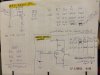
The circuit I now have is controlled by a 7 day timer which closes a 120 volt SPDT relay which then operates several 12 volt devices. (This is another chicken coop door closer:D).

When the timer is on (Day) the NC contacts of the relay open and remove 12 volt power from the signal wire of a car power antenna (mounted upside down) and pull the vertical sliding door open. As soon as the door is open the antenna limit switch stops power usage.

When the timer is off (Night) the NC contacts close and the antenna closes the door. It also lights a LED (that I can see from the house so a look out the window tells me all is well) .

Even though I have replaced the relay twice, the last time w/ a good one, I still have problems w/ it sticking once in a while I.E. the door doesn't open in the morning (BAD if I'm out of town as there is no food or water inside the coop)! At one point it was the limit contacts in the antenna that were causing trouble but I've cleaned and oxgarded those and they have been working fine. I don't understand why this is so troublesome as the 12 volt current is minimal. The relay does get quite warm when it's continually on during the day.

I'm thinking of replacing the relay with a MOSFET switch. It would have to be triggered by a dedicated AC input or homebrew optocoupler.

????s
I believe it would need a capacitor to hold the MOSFET input steady during the AC phase shifts. AM I RIHGT? If so I do not know how to calculate capacitor size and if it would also need supporting components to accomplish this. Maybe a diode in series w/ the capacitor-ground leg and a bleed off resistor. I could just start prototyping but a little guidance would sure be helpful.

I could also build a dedicated PIC or Propeller clock circuit w/ LCD readout but the timer is so easy to set and use and I'm busy doing many other things too!

Another thought as I'm writing this>>> There is probably a latching relay available that would not need continuous power but that seems like it would need other controls.

Thanks for your time
Aaron

PS I've been away for a time programming Propellers but have not forgotten my PIC roots:)
 
I dont quite get how your doing this, you have an ac supply with a 12v electric car antenna, and the relay is ac, is that correct.
One avenue is improve what you have, relay contacts burn when switching an inductive load, you can reduce this and make the contacts last a lot longer by putting a suppressor across the contacts, you can buy them pre made for ac motors, or you could use a 100nF class x cap in series with a 100 ohm 1 watt resistor.
Or how about replacing the relay with a solid state relay.
 
>>> ac supply with a 12v electric car antenna, and the relay is ac, is that correct.
Yes

>>> replacing the relay with a solid state relay
Solid state relay with AC input? Do you have a part # in mind?

>>>100nF class x cap
I'm not familiar w/ that type cap

Thanks dr pepper
Aaron
 
Does your timer have any volts-free output terminals? Can you post a link to the timer?
 
Assuming you are now using a relay with a 120Vac coil to switch a 12Vdc motor, you can obtain a "Solid State Relay" that will substitute for the mechanical relay, however you may not like the cost.

You could also use an opto-isolator whose input side is designed for 120Vac, and whose output side can switch the gate of MOSFET wired to control the motor.
 
Does your timer have any volts-free output terminals? Can you post a link to the timer?
It's just a plain, plug into the wall, 7 day programmable with a 120 volt grounded outlet on the side

... You could also use an opto-isolator whose input side is designed for 120Vac, and whose output side can switch the gate of MOSFET wired to control the motor.
That's what I was asking about in post#1 paragraph 6. How would that circuit look? Are you the Mike who used to live in Michigan?

Thanks
Aaron
 
Here's a relatively inexpensive Chinese DC output SSR
You just have to add a DC output wall-wort plugged into the timer to provide the 3-32Vdc to turn it on.
 
Last edited:
Hi AGCB,

Below is a circuit for an isolator between your mains timer and 12V power supply. The components are all freely available and low cost: total about $4US.

spec

2016_10_29_iss03_ETO_MAINS_TIMER_ISOLATOR_VER1.png
ERRATA
(1) None
NOTES
(1) C3 is Ceramic X7R dielectric, +- 20% or better, 18V working or higher, thru-hole (not surface mount) C3 can also be polycarbonate.
(2) C2 is polyester or polycarbonate dielectric, +- 20% or better, 200V working or higher, thru-hole
(3) Resistors are metal film or metal oxide, 0.5W or better, thru-hole, 200V or higher, unless otherwise stated.
(4) R5 can be wire-wound or ceramic, 3W or greater +-20% or better, 200V or higher.
DATA SHEETS
https://www.infineon.com/dgdl/irf4905pbf.pdf?fileId=5546d462533600a4015355e329b1197e
**broken link removed**
https://www.vishay.com/docs/88503/1n4001.pdf
 
Last edited:
Thanks spec

In paragraphs 2 & 3 of post #1, the reason I did it with the NC contacts was so that if the mains power went out at night the door would remain closed.

From what I can see in the schematic, if the mains power went out it would result in no 12 V power at the output and the door would open.

My brain is a little foggy this morning but I think this could be changed. Maybe a N-channel MOSFET (lo side switch) and possibly needing a PNP transistor to reverse the output polarity of the OPTO or possibly just reversing the leads. Do we really need a darlington OPTO? I have several 4N26

Am I making any sense? Good chance not!

I think the same problem exists with using a SSR as crutschow suggests because there is only NO contacts

Aaron
 
Last edited:
Thanks spec
My pleasure.:)

In paragraphs 2 & 3 of post #1, the reason I did it with the NC contacts was so that if the mains power went out at night the door would remain closed. From what I can see in the schematic, if the mains power went out it would result in no 12 V power at the output and the door would open.
Got it. I didn't fully understand how the door opening and closing worked, but nothing that can't be sorted.

Do we really need a darlington OPTO? I have several 4N26
4N26 will almost certainly be OK.

I will establish how the door opens/closes and do a revised circuit, but the complexity and general topology will be similar to the circuit of post #8.

spec
 
Hi again AGCB,

Just a few question about the door operation.

What is the supply that closes the door? Is it a battery?

Is it correct that if the 12V supply fails that the door will open?

Is all that you want is for the circuit of post #8 to switch the PMOSFET on when the timer contact is open, or is there more to it than that?

spec
 
Hi again AGCB,

Just a few question about the door operation.

What is the supply that closes the door? Is it a battery? Yes, 12 volt

Is it correct that if the 12V supply fails that the door will open? No, no power to the antenna, nothing happens. The antenna has 3 leads, +, -, and signal. + & - are constant. In the car, when you turn on the radio, 12 volts is applied to the signal wire and the antenna goes up (in my case the antenna is upside down so the door closes down). When the radio is turned off the opposite happens. Besides the motor w/ limit switches the antenna has a DPDT relay

Is all that you want is for the circuit of post #8 to switch the PMOSFET on when the timer contact is open, or is there more to it than that? That's it!

spec

Thanks spec
 
ACGB, will this do your job:

2016_10_29_iss1_ETO_MAINS_TIMER_ISOLATOR_VER2.png

I did the above circuit before I got your post #12 above, where you say that all you want is for the PMOSFET to turn on when the timer relay opens. If that is all you want, PMOSFET Q3 and C5 (220nF) can simply be omitted.

spec

ERRATA
(1) Connect additional 220nF capacitor between Q4 source and 0V, as C5 is connected between Q3 drain and 0V.

NOTES
(1) 12V SWITCHED = 12V when the timer contact is made
(2) 12V SWITCHED = open circuit when the timer contact is open
(3) /12V SWITCHED (means, NOT 12V SWITCHED) = open circuit when the timer contact is made
(4) /12V SWITCHED = 12V when the timer contact is open
(5) NMOSFET BSP296 (Q3) is obsolete. Substitute Si2308BDS if necessary

DATASHEETS
(1) https://www.vishay.com/docs/83725/4n25.pdf
(2) https://www.vishay.com/docs/88503/1n4001.pdf
(3) https://www.infineon.com/dgdl/irf4905pbf.pdf?fileId=5546d462533600a4015355e329b1197e
(4) https://www.farnell.com/datasheets/45992.pdf?_ga=1.201408665.942089101.1451155200
(5) **broken link removed**
 
Last edited:
spec
So as you have it drawn w/ the 3 MOSFETs , it's like a SPDT relay. By removing Q3 it becomes like a SPST. Correct?

I've made some logic level MOSFET switches using a bipolar transistor to change the output polarity of whatever and increase gate voltage to the MOSFET.

Could I substitute an IRF510 for Q2 because I have them on hand?

Aaron
 
After some further thought, I think your original problem is arcing of the relay contacts due to the inductance of the antenna signal load (which I suspect is a relay coil).
This arcing burns the contacts which can cause them to weld and stick.
To eliminate this just add a diode for arc suppression at the relay contact that goes to the antenna (diode cathode) with the anode to ground.
You can use just about any 1A or greater rectifier diode such as a 1N400x (x=1-7).
 
Last edited:
So as you have it drawn w/ the 3 MOSFETs , it's like a SPDT relay.
Yes, similar.

By removing Q3 it becomes like a SPST. Correct?
Yes, that is correct.

I've made some logic level MOSFET switches using a bipolar transistor to change the output polarity of whatever and increase gate voltage to the MOSFET.
Not too sure what you mean here- could you post a schematic?

Could I substitute an IRF510 for Q2 because I have them on hand?
Yes, an IRF510 will be fine.

spec


DATASHEETS

**broken link removed**
 
Not too sure what you mean here- could you post a schematic?

Slightly off topic but I was just looking at how you used a MOSFET similar to how I have used a bipolar transistor in the input circuit of a MOSFET.

Shown is a page from my notebook as I was learning/testing a way to use a non logic level MOSFET in the output of a MC when no logic level device was on hand. As I proved to myself, a non logic level device wont work with a low signal input but can be made to work with a few additional components to boost the input signal. I'll have to play w/ MOSFETs more!

Thanks spec, crutschow and others.
I've learned and must now test!!!

Aaron
 

Attachments

  • DSCF1701.JPG
    DSCF1701.JPG
    1.8 MB · Views: 233
Slightly off topic but I was just looking at how you used a MOSFET similar to how I have used a bipolar transistor in the input circuit of a MOSFET. Shown is a page from my notebook as I was learning/testing a way to use a non logic level MOSFET in the output of a MC when no logic level device was on hand. As I proved to myself, a non logic level device wont work with a low signal input but can be made to work with a few additional components to boost the input signal. I'll have to play w/ MOSFETs more!
Hi AGCB,

You are obviously are an engineering type.:cool:

The IRF9520 is a nice PMOSFET, but it has a relatively high gate threshold voltage of 4V worst case, and a high drain/source on resistance of 0.6 Ohms worst case, compared to the latest PMOSFETS. But the IRF9520 is still a very useful device: 100VDS, 6.8A ID, 0.4 Degrees C Watt thermal resistance (extraordinarily low for a medium power MOSFET), and available in an easy-to-use TO220 case.

A comparable later PMOSFET, would typically have a worst case gate threshold of 2.5V and a much lower on resistance of around 0.05 Ohms. But the maximum drain source voltage would be less at 20 to 50V, with 20V being very common. The new devices are only available in surface mount cases though.

Yes, as you show with your notes, you can make a voltage amplifier/inverter/translator with a bipolar junction transistor (BJT). In fact, Q2 in the circuit of post #13 could be replaced by an NBJT and two resistors.

Your NBJT translator has an input voltage threshold of around 400mV (base/emitter turn on for silicon transistor) and a fully conducting input voltage of 600mV (ignoring base current). You can change the input voltage threshold of a BJT translator by using two resistors on the input rather than one. In your translator, if you added a 10K resistor from the base of the transistor to 0V, the input threshold would be multiplied by two, so would become 0.8V. Of course, you have to ensure that there is sufficient base current drive to generate the required collector current.

With a MOSFET there is no gate current (at DC) to worry about, but the gate threshold voltage is not as well defined as for the base threshold voltage of a BJT. Typically a MOSFET gate threshold has a two to one variation, from device to device. For example, the gate threshold voltage spread for an IRF9540 is 2V to 4V. You can also multiply the threshold voltage of a MOSFET translator with two resistors.

MOSFETS are dead easy, but the fun starts at high frequencies, when you have to cater for the massive parasitic capacitances, and at high currents where you have to watch out for heating and secondary break-down. It is ironic that, although a MOSFET gate takes no current at DC, at high frequencies a MOSFET may take more gate current than an equivalent BJT would require base current.

Special gate driver chips are produced to cater for the effective high input capacitance of MOSFETs. There driver chips have an extraordinarily high current drive capability of 1A to 7A (see LM5110 data sheet below).

Incidentally, the two PMOSFETS in the circuit of post #13, could be replaced by BJTs, but not without some other circuit modifications.

End of lecture.:D

spec


DATASHEETS
https://www.vishay.com/docs/91074/91074.pdf
https://www.ti.com/lit/ds/symlink/lm5110.pdf
 
Last edited:
spec
Thanks for the info.
Your knowledge is way beyond my self taught hobby stuff. I looked at the data sheets and compared specifications. Things I had not noticed before and interesting.
Aaron
 
spec
Thanks for the info.
Your knowledge is way beyond my self taught hobby stuff. I looked at the data sheets and compared specifications. Things I had not noticed before and interesting.
Aaron
Thanks AGCB: but I suspect you are underestimating your skills. It is not what you know that counts; having a logical approach is the most important thing. The data sheet is always the key. Many circuits are meaningless without them.:)

spec
 
Status
Not open for further replies.

Latest threads

New Articles From Microcontroller Tips

Back
Top