Continue to Site

Welcome to our site!

Electro Tech is an online community (with over 170,000 members) who enjoy talking about and building electronic circuits, projects and gadgets. To participate you need to register. Registration is free. Click here to register now.

  • Welcome to our site! Electro Tech is an online community (with over 170,000 members) who enjoy talking about and building electronic circuits, projects and gadgets. To participate you need to register. Registration is free. Click here to register now.

Relay switching causes reset

Status
Not open for further replies.

kybert

New Member
Hi,

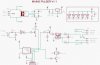
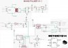
I've attached my circuit. When the relay turns OFF, the PIC resets - i think due to a power brown-out, but cant be sure of this.

When the relay is energised, all is fine.


I have added a 470uF cap to the 12V rail (not shown) with no effect, and also a 100uF cap to the 5V rail (not shown), also having no effect.


Help!
 

Attachments

  • cir.jpg
    cir.jpg
    42.7 KB · Views: 602
Did you pull up MCLR_n with a resistor? Also make sure you do not have LVP enabled (your chip probably doesn't even have this).

Also do you have the WDT enabled? Be sure your code does not get into a loop which doesn't clear wdt in it. Make sure your code always loops back somewhere when it gets to the bottom of your code, otherwise it'll just run off into uncoded program space (the wdt usually catches this).
 
Hi thank for the suggestions..

The MCLR pin is configured as an input pin in this case so the MCLR function of the pin is disabled.

The code simply energises the relay, then flashes the triac 10 times (at 250ms intervals) then turns off the relay - at which point the device resets.

Code:
	#define EnableRelay();		gpio |=  0x10;				// Set bit
	#define DisableRelay();		gpio &= ~0x10;				// clear bit
	#define EnableTriac();		gpio |=  0x20;				// Set bit
	#define DisableTriac();		gpio &= ~0x20;				// clear bit

//~//

	EnableRelay();
	delay_s(1);
	for(x = 0; x < 10; x++)
	{
		EnableTriac();
		delay_ms(250);
		DisableTriac();
		delay_ms(250);
	}
	DisableRelay();

	// we dont get stuck here because the device resets !
	for(;;);


I have been measuring signal levels around the circuit and the reset only occurs if the schmitt trigger input is connected to 12V and the relay is switched off, but when this happens my meter says that the schmitt o/p (pin 2) remains low (as expected) and the PIC input pin (pin 5) remains high (as expected).

Whe WDT is also disabled.
 
Where are your unused pins at? With CMOS IC's you need to put all unused inputs to Ground (VSS) OR Positive (VDD) otherwise erratic chip behavior and excessive current consumption will occur.

Also A grounded Soldering Iron must be used with all Static Sensitive Devices or Stray Static will dammage the IC.

Use Aluminum Foil to set the IC on when you are putting your Parts together. Just set the IC pins down on the Foil when not Installed. Also Discharge yourself to a Ground Point like a water pipe or the ground Lug in the outlet before touching the IC.
 
In the top-right corner of my circuit, i show all un-used input pins on the schmitt trigger device as connected to 12V.

I am aware of the static nature of CMOS devices, and i am sure that the device is not broken because it is performing as it should (as far as i know)

The problem appears to be with the relay turning off when the schmitt trigger input is connected to +12V.

Under these conditions the PIC resets and i cant work out why becase all the input pins on the PIC appear to be at known good stable levels.
 
kybert said:
In the top-right corner of my circuit, i show all un-used input pins on the schmitt trigger device as connected to 12V.

I am aware of the static nature of CMOS devices, and i am sure that the device is not broken because it is performing as it should (as far as i know)

The problem appears to be with the relay turning off when the schmitt trigger input is connected to +12V.

Under these conditions the PIC resets and i cant work out why becase all the input pins on the PIC appear to be at known good stable levels.

It might be transient in nature.. when you make your measurements, everything is stable right? Can you take a look at the 5V supply right at the PIC pin with a scope to capture what happens at the exact moment the relay turns off? Are there spikes? is it drooping very low?

Can a low 5V voltage on the pic cause it to reset?

Is the schmitt trigger powered from 12V ?
 
Optikon said:
Can a low 5V voltage on the pic cause it to reset?

Of course it can, that's how it's supposed to work - 'brown out' circuits are designed to make it reset more effectively under these conditions as well.

As you say, you need to be absolutely sure the HT rail isn't momentarily dropping.
 
hI,

I've found the bug, it was a compiler bug in the 'C' compiler that i'm using.

It allowed code to continue to execute into unporgrammed memory space, which in turn caused the device to reset! :shock:

Ive reported the bug.


Many thanks to all that helped... The compiler was the last thing that i suspected as the fault!


Whilst were here, does anyone see anything wrong with the circuit before i request another PCB revision to be made?


Joe
 
Similar Problem

Hi,
I had the similar problem of the above scenario of getting affected by the relay switching.
When the relay is off is may affect others channels. Only during off this will happen. I do not have any scope to monitor the supply lin eif it drops below certain level that cause the Pic to reset. I built several others similar board and link via RS485. The relay[off] action can cause some problem to others channel of the same device. And it happen to affect the next connected module as well. I share one 12Vdc adapter to 3 similar board with difference Address hardcoded into the Pic. The adapter rated at 12Vdc (regulated) 3.5A which I presume to be sufficient for three board. Each board had eight 12V G5LE relay (coil current 33.3mA).
I'm more suspicious about my hardware design rather then the coding that cause the problem.
LVP/Watchdog is disable in my programme.
Attached is the design i used. Would it be my design problem?
Regards
Alvin
 

Attachments

  • rel8a_sch.png
    rel8a_sch.png
    13.5 KB · Views: 276
Besides, I think i had some problem with the PC receiving data from the PIC data. Sending data command to PIC is working fine. But not the other way round. Can my circuit work with that simple inverting circuit?

Regards
Alvin
 
Long journey?

Hi John,

glad to see you around here after a long time.

You certainly remember me from another forum as "HtG" also called Hans. :)

Regards

Hans
 
Status
Not open for further replies.

Latest threads

Back
Top