Insipid
New Member
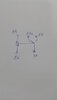
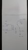
I don't quite get the relay in this diagram. Hell, I don't get the whole thing really.Connect the circuit this way.
When the trigger is 0v, the relay will energize.
When the trigger is 12v, the relay will de-energize
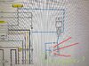
View attachment 127733