Continue to Site

Welcome to our site!

Electro Tech is an online community (with over 170,000 members) who enjoy talking about and building electronic circuits, projects and gadgets. To participate you need to register. Registration is free. Click here to register now.

  • Welcome to our site! Electro Tech is an online community (with over 170,000 members) who enjoy talking about and building electronic circuits, projects and gadgets. To participate you need to register. Registration is free. Click here to register now.

Relay Required

Status
Not open for further replies.
Your circuit has an error. Disconnect area in red, add my drawing that is in black. You need some type of load to complete the circuit in the simulation so add a 10 ohm to 10k ohm resistor to complete the circuit (circle).

View attachment 127719
Did exactly what you sent, not working :( 
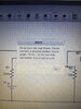
, i can see here in this drawing 3 components 1 MOSFET, 1 Resistor 100k ohm on Gate, 1 Resistor 100 ohm on Drain correct ?
 

Attachments

  • 16040274620336511757725973006041.jpg
    16040274620336511757725973006041.jpg
    3.8 MB · Views: 169
Your mosfet is "upside-down". It should be like this...
A3C17F69-206B-4BBD-9BDA-E5E319F0F310.jpeg
 
Last edited:
Deleted
 
Again, tried the circuit , no ground and not working

Please i need the exact components and exact circuit
 

Attachments

  • 16040312453711530762920552234965.jpg
    16040312453711530762920552234965.jpg
    6.7 MB · Views: 152
  • 16040312608816751225660232753970.jpg
    16040312608816751225660232753970.jpg
    2.8 MB · Views: 150
And change your 100k gate resistor to 10 to 1k.
 
And add the ground icon and connect to the node shown.

87A676FC-723E-4CB7-BB44-D9EBC96274DB.jpeg
 
And change your 100k gate resistor to 10 to 1k.
Please do not change my design.
Leave at 100k ohm.
I put that in there to minimize the effects of any transient voltages.
It won't slow down the FET enough to make a difference in this application.
 
Please do not change my design.
Leave at 100k ohm.
I put that in there to minimize the effects of any transient voltages.
It won't slow down the FET enough to make a difference in this application.

I was just wondering why his simulator is having trouble - it was the last thing I could come up with.
 
While I doubt that this is the cause of the simulator errors you're getting, the MCH3383 mosfet that you have in your circuit is not suitable for your application.

It's maximum drain-source voltage is only 12 Volts. The voltage is a vehicle when running is typically 14 to 15 Volts.

I suggest a part with a Vdss rating of at least 30 volts. Personally, I would use a 60 volt part.

Also, you said that your trigger signal is coming from a relay. When it's not at 12 volts, is it actively connected to ground, or just not connected to 12V? If it's just not connected, then the p-mos circuits described above will need a pull down resistor at the input.

Exactly, When it's not 12 Volt, it's Never Ground, the voltage just drops to 100mv which is almost nothing

what is pull down resistor that i need to put ?

and if i'm having a problem in my simulator, can you tell me the simulator you are using, I'm using online partsim simulator

please if you can just a simple drawing of the circuit with the components and the simulator name so i can test it

sorry i'm so much a beginner

thanx
 
Hello

I'm sorry i'm not experienced in circuits but i want a very simple circuit but don't know how to do it

this is a car circuit, so only 12 volt components, and no current load will be there, it's only for trigger wire, very low current required

i want a SMD relay number and design to do this

i have a wire which is having constant 12 volts

in certain condition when this wire voltage goes back to zero, i need the relay to supply me with with 12 volts wire and once 12 volts comes back to the original wire so relay cut off and gives 0 volts

please help me with the components required please, i need a small component not a large bulky relay

thanx

Connect the circuit this way.
When the trigger is 0v, the relay will energize.
When the trigger is 12v, the relay will de-energize

1604062091173.png
 
Connect the circuit this way.
When the trigger is 0v, the relay will energize.
When the trigger is 12v, the relay will de-energize

View attachment 127733

Just For Confirmation
the required components are only 4 components

A)
P-MOSFET 30 - 60 Volts 5 amperes
B) 1 resistor 100k ohm to be connected to between source and gate terminal
C) 1 resistor 100 ohm only to be connected to between gate terminal and alternating voltage wire (0-12 volt)
D) 1 diode 1N4007 between the drain and the device to be activated by the output from MOSFET

and for ground wire ofcourse all the car devices are powered from same ground so only 12 volts wires to be connected?

please confirm

thanx
 
A) P-MOSFET 30 - 60 Volts 5 amperes
B) 1 resistor 100k ohm to be connected to between source and gate terminal
C) 1 resistor 100 ohm only to be connected to between gate terminal and alternating voltage wire (0-12 volt)
D) 1 diode 1N4007 between the drain and the device to be activated by the output from MOSFET

and for ground wire of course all the car devices are powered from same ground so only 12 volts wires to be connected?
A) Yes.
B) Yes
C) Use 1k ohm for pull-down (if it's needed) and connect it from the 100k ohm input to ground.
D) Diode is only needed if you are driving an inductive load, such as a relay coil.

Besides the 12V signal, you also need a ground connection for the 1k ohm pull-down resistor.
 
Just For Confirmation
the required components are only 4 components
no. If you include the relay then there are 5
A) P-MOSFET 30 - 60 Volts 5 amperes
Amps = 100% over the required relay current. If the relay requires 100 mA, then a 30-60v, 200mA mosfet is needed (minimum)
B) 1 resistor 100k ohm to be connected to between source and gate terminal
Yes. This ensures the mosfet turns off when the input voltage is at 12v
C) 1 resistor 100 ohm only to be connected to between gate terminal and alternating voltage wire (0-12 volt)
Yes. I've shown a square wave "trigger" signal so it would be easy to see the activity.
D) 1 diode 1N4007 between the drain and the device to be activated by the output from MOSFET.
If you add a relay, the diode surpresses the back EMF generated by the relay coil that could damage the mosfet or induce improper behavior in nearby circuits. The relay contacts would need to be able to handle the load capacity of 5Amps (I think that was the required current(?))
and for ground wire of course all the car devices are powered from same ground so only 12 volts wires to be connected?

please confirm

thanx

Yes
 
Last edited:
i got the P MOSFET IRF9640 and resistors

tested without soldering the pins to the resistors and it was working fine and did the job nicely

once i soldered the pins to the resistors and tried to test it, it didnot work

removed everything and tested the MOSFET again it didnot work

this happened in 2 MOSFETS, i think both are damaged now

does soldering heat damage the MOSFET ?
 
does soldering heat damage the MOSFET ?
It can do, if prolonged. Also, MOSFETs can be damaged by electrostatic discharge and so need careful handling. (Google for precautions you can take).
 
i got the P MOSFET IRF9640 and resistors

tested without soldering the pins to the resistors and it was working fine and did the job nicely

once i soldered the pins to the resistors and tried to test it, it didnot work

removed everything and tested the MOSFET again it didnot work

this happened in 2 MOSFETS, i think both are damaged now

does soldering heat damage the MOSFET ?

What are you using to mount the parts? perfboard?
 
If the soldering iron has any leakage current from the mains, it can damage the MOSFET gate.
 
Status
Not open for further replies.

New Articles From Microcontroller Tips

Back
Top