Continue to Site

Welcome to our site!

Electro Tech is an online community (with over 170,000 members) who enjoy talking about and building electronic circuits, projects and gadgets. To participate you need to register. Registration is free. Click here to register now.

  • Welcome to our site! Electro Tech is an online community (with over 170,000 members) who enjoy talking about and building electronic circuits, projects and gadgets. To participate you need to register. Registration is free. Click here to register now.

Relay help.... ?

Status
Not open for further replies.

yusuf

Member
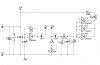
Friend I have here a water sensor circuit and I want that if the water level touches this sensor then it will drive a relay which will turn off the Motor pump...
And as the water level goes low means below the water sensor then it should turn on the motor pump...

I have 12volt and 200ohms relay... with 10 ampere contacts....

Guys how should I drive motor pump with relay please provide help....
So please provide a circuit diagram or modify this one so that it can turn on/off the motor pump...
 

Attachments

  • WATER-PROBE.png
    WATER-PROBE.png
    28.5 KB · Views: 183
A problem with that circuit is that is will "short cycle"...turning the pump off and on and off rapidly as the water level changes a small amount. You would need to add a time delay for hysteresis, or better, a second probe circuit and a flip-flop. The high probe sets the F-F turning the pump off. The low probe resets the F-F, turning the pump on. I saw one using that basic circuit...but I can't find it. :(

Ken
 
Last edited:
Friend please help... I have posted this circuit diagram above because I have tested this with the Led in water for 1 month and it worked corrosion free... now I am thinking to turn ON/Off motor pump so please help....

I dont want low level circuit I just want that as I put this circuit probe sensor in water it switch off the motor pump and as the water goes low below this sensor then it will turn On the motor pump...
 
Last edited:
Your circuit is good for an indicator. But with it, the pump will switch off as soon as the probe touches the water. This may cause sloshing. The probe is then briefly out of contact with the water and the pump will restart. This can also cause sloshing and repeats the cycle over and over very rapidly. A second, lower probe with a flip-flop will prevent this, with only a few more components. This is how I remember it: attached.

I actually use a version of this, except with a micro-controller instead of a flip-flop, to automatically maintain water in a Christmas tree stand.

Ken
 

Attachments

  • WaterLevelPumpControl.gif
    WaterLevelPumpControl.gif
    29.3 KB · Views: 158
Last edited:
you have to use another probe as KMoffett said, it seems yo have no idea of how it shoudl work. i have a working circuit too, its with NAND gates only. no capacitor required, if you are interested tell me..
 
Dear KMoffett thanks.... you very much but is this corrosion free circuit diagram......
and what is the diode number.... please give.... or can I use IN4148 diode...

and mbarazeen you can also give me your circuit diagram....
 
Last edited:
Dear KMoffett thanks.... you very much but is this corrosion free circuit diagram......
and mbarazeen you can also give me your circuit diagram....

This is as "corrosion free" (AC vs DC) as you will get with a "conductive liquid" circuit. Normally I would use 316 stainless steel TIG welding rods for the electrodes, but platinum or gold would be even better. For absolute "corrosion free", you would have to find a non-contact sensing system.

Ken
 
OK but which diode will I use ... you have not mentioned diode number.......
 
And KMoffett I also want to add a timer in this circuit...... so please read what do I need from this circuit carefully below :

As the water goes below the low level sensor it will start motor pump and wait for 10 minutes... in between 10 minutes if the water goes little bit higher so that it touches low sensor then the motor will keep on running untill the tanks becomes full (so that water touches full sensor) if the tanks becomes full the it will stop the motor pump...else if the water doesnt comes lit bit higher so that it can touch low level sensor between 10 minutes then motor pump will turn off... and it will start again after 1 hour and this process will repeat.... untill the tank becomes full..

friend I want this same concept so please help me how should I accomplish this..... As per my knowledge I hope that we want timer... but I hope you can think better ... so please ....... help ?
 
Last edited:
D1-D4 are BAT85 Schottky diodes, and D5 is a 1N4001 silicon diode as shown in the schematic in post #4.

As for your "new" requirements...its time to dump the simple logic-gate solution and go to an 8-pin microcontroller. This means that you need to get into programming. I used a PICAXE 08M on my water level controller. PICAXE-08M2 is as low as $3.50US each. https://www.picaxe.com/ BASIC programming software for Windows is free. Minimum programming setup is: the chip, 2 resistors, 4.5V battery, and a homemade serial port cable. There is also a very supportive and civil users' forum:**broken link removed**

Ken
 
Ok please give the complete circuit diagram of the microcontroller which you have used in your tank.please give the complete circuit diagram with sensor..
Thanks
 
https://www.picaxeforum.co.uk/showthread.php?12266-08M-Christmas-tree-watering-controller
You'll have to register as a new member...but it's free! ;)

The hardware would be pretty much the same. If you wanted to use an electromechanical relay instead of an SSR, there would need to be changes. Timing would have to ba addad to the program.

Also, that PCB did not allow for on-board programming. The chip was programmed on a breadboard and then plugged into the PCB.

Ken
 
Last edited by a moderator:
Friend but what I need i didn't got... so please kindly have a look on my previous post.... and provide a circuit diagram soon...

Urgent help required to complete the project...
 
You need to register in the forum to get all the info in the thread. Program is in post #1 (rewrite by MPep in post #4). Schematic and PCB layout in post #11.

And why is this "urgent"????

Ken
 
Last edited:
Thanks for your reply friend... but can you send me the complete program with timing code...
as I have posted...

And friend I have created and activated my account by I does not access to the circuit diagrams while opening circuit diagram I am getting
---" you do not have permission to access this page. This could be due to one of several reasons: Your user account may not have sufficient privileges to access this page. Are you trying to edit someone else's post, access administrative features or some other privileged system? "-----

So please can upload here for me so that I can access here... and please send me the complete code with timing program....

And how did you program with home made serial cable... please suggest this also...

thanks in advance....
 
Last edited:
It may take a little while for the forum administrators to authorize your access.

So you want me to do a revised schematic, a revised PCB layout, and rewrite and test my program for your timing ...and you're not even not willing tell me why it's so urgent? :( You've been working on this (at least 4 threads, maybe more) since July.

The serial cable layout can be found in Section 1 of the Manuals https://www.picaxe.com/Getting-Started/PICAXE-Manuals/

Ken
 
Last edited:
Friend it is urgent because I have only got 5 months to complete and I have only one month left.. so I was telling that it is urgent because I dont have enough time....
If my words has hurt you then I am extremely sorry my friend..
 
Hello KMoffett I have got the circuit diagrams of PICAXE but please give program code as I want in my project...
 
Status
Not open for further replies.

Latest threads

New Articles From Microcontroller Tips

Back
Top