Continue to Site

Welcome to our site!

Electro Tech is an online community (with over 170,000 members) who enjoy talking about and building electronic circuits, projects and gadgets. To participate you need to register. Registration is free. Click here to register now.

  • Welcome to our site! Electro Tech is an online community (with over 170,000 members) who enjoy talking about and building electronic circuits, projects and gadgets. To participate you need to register. Registration is free. Click here to register now.

Regulated 12VDC from car

Status
Not open for further replies.

gtr33m

New Member
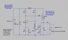
I have a pc power supply which runs a small pc using a 12VDC input. This works fine when run off the car battery, but sometimes has problems when the engine is running and the alternator is producing 13.8VDC.

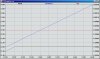
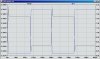
Is there something simple I can do that will regulate the voltage to 12VDC +- 0.5?

I would guess that the current will be somewhere around 1A

Thanks.
 
Its called a "low dropout" regulator. Most of the the 7812 types have a dropout voltage of ~2V, which is too high for your application. I have built a 14.2V SoLAR panel PFET battery charger regulator which has a dropout voltage of only 0.2V. We could adapt it to put out 12V from 12.2+V.
 
I assume that LDO is some sort of acronym for a low dropout regulator, correct.

Is this something that I can easily build, ie solder a few parts together purchased from the local components place (Jaycar here in Australia), or am I better or to purchase one complete?

I ultimately need 12v and 5v to power the pc, and the power supply that I have (which needs the 12v regulated supply) is overkill, so maybe I should be looking at something else entirely?
 
Are you sure that it's the voltage and not all the other transients present? A car battery is usually over 13v when charged anyway, and I doubt a small laptop is going to present enough of a load to drop it much.
 
I have measured many recent model cars. With the engine running at 1200+rpm, the electrical bus is at 14.5 to 14.8V, depending on temperature.

Here is my home-brew Low Dropout Regulator. Parts should be relatively easy to obtain. The PFET is not particularly critical. The PFET dissipates up to 5W, so it needs to be mounted (using an insulating mounting kit) to something metallic, like the car body.

There are two plots shown. The first is a sweep of input voltage from 12 to 14V. Note that the min. drop across the PFET is only 200mV at 2A. The second shows the dynamic recovery of the regulator as the load current switches from 0.1A to 2A.
 

Attachments

  • 12Vreg.jpg
    12Vreg.jpg
    74.6 KB · Views: 1,589
  • 12VregSweep.jpg
    12VregSweep.jpg
    159.6 KB · Views: 449
  • 12VregStep.jpg
    12VregStep.jpg
    151.3 KB · Views: 434
Thanks Mike.

I'm a novice, but I think I can follow your design as it seems fairly simple. Can I pm you if I have some issues?

If I wanted to do away with my current power supply altogether and use your circuit, what would I need to do to also supply 5V? I'm pretty sure that the 5V will draw almost no current, maybe 500mA, though I'll have to measure it to make sure.
 
Will post any questions I have here when building.

FYI, the voltage change on the car that I am using the PC on is about 2 volts, 12-12.1VDC when off and as high as 14.2VDC when he alternator is running hot. This is enough to cause the PC to shtudown or reboot intermittently.
 
You should check to see if you can buy a LDO regulator of this type designed for automotive use.

There are a lot of nasty things that go on in a cars electrical system. The DIY job could well fry the PC some day.

I can vouch for both statements above. There are all sorts of noise and voltage transients occuring in a vehicle.

They may be infrequent, and they may be short period, but they pack a lot of energy. I've personally seen LM78xx regulators with their tops blown off.

The society of automotive engineers has a very comprehensive spec with respect to voltage transients in automotive environments.
 
There's nothing wrong with the home made schematic.

Just make sure the BJT and MOSFET are good enough for 100V.

Adding a zener between the gate and source of the MOSFET will also help to make it more robust.

A 15V zener across the output terminals will also help protect the device connected to it.

Current limiting can be received by adding a couple of transistors (at the expense of adding about 600mV on the to the drop-out) or a polyfuse (assuming the MOSFET can take the surge for long enough for the polyfuse to protect it).
 
I'm going to try building one, if for no other reason than it will be a good one for me o cut my teeth on.

My local electronic parts place has 2 LDOs which seem to suit

**broken link removed**

and

**broken link removed**

The second seems to be the better choice as it has a lower dropout and can handle more amps. Can anyone confirm this for me?
 
The 2940 is specifically built for automotive applications, while the 1085 is not. The 2940 automatically shuts down if the input voltage exceeds 30V, thereby protecting itself and your load. It also isolates the load in the event that the car battery polarity is reversed.

The specific events that the 2940 protects against are caused by stupidity; installing the car battery backwards, jumping it backwards, jumping a 12V car with a 24V battery, or disconnecting the battery with the engine running (load dump).

Assuming you are not that stupid, then either my circuit or the 1085 will work just fine, the naysayers notwithstanding. :eek:
 
My two cents.

Everyone is free to do as he or she pleases. Having said that.

Purpose made parts tested by engineers are a dollar or two, so cost is not an issue.

Sounds odd that you want to gamble with your laptop.

3v0
 
3v0

I take what you say on board and agree 100%, not just because of the potential failure, but also because of the amount of time troubleshooting a home made anything that just doesn't seem to work right.

In this case however, I'm talking about an old surplus single board pc that cost me $50, so I'm willing to give it a try. The worst case scenario is not going to be disasterous and it will be a good learning tool for me.

I am a complete novice when it comes to this stuff, having the skills to solder and my experience being limitted to building kits from detailed instructions, often without success, so... Hero999 would it be possible to give a noob a bit more information on the modifications you suggest?

I think I can build the circuit as shown in the diagram, and I'm ok with putting a 15v zener across the output terminals, but where should I be putting the one between the gate and the MOSFET?

Thanks for all the advice everyone, it's been really helpfull.
 
Last edited:
I've just downloaded the spec sheet from the pc and there is another option. The pc will operate on 5VDC with a draw of 3.89A.

This would do away with the need for the 12VDC power suppy that I intended on using, so I may look at this as an alternative.

I'm still going to build the 12VDC LDO as it will be usefull for other things and I will use it with my existing power supply for the moment, but... using my very limited knowledge and a simple application of ohms law the pc will draw 19.45W @5V/3.89A

It looks like LM2940CT looks to be only 1A so can only handle 12W. Assuming no loss, it would still be 7.5 W under powered, which means I will have to us the LM1085IT which is 3A.

Is my math at least partially right or have I stuffed it somewhere?
 
Just to throw another spanner into the works, I've had a look at the 1085 datasheet, and I see that there is a LM1805-5 which will regulate to 5V at a peak of 5A. According to the typical applications the only change (other than the LDO) is a couple of extra resistors.

Could I not use the same circuit for a 5V supply or even better use both with switch for switchable 12V or 5V. I might be getting ahead of myself, but I'm exploring ideas.
 
Status
Not open for further replies.

Latest threads

New Articles From Microcontroller Tips

Back
Top