Continue to Site

Welcome to our site!

Electro Tech is an online community (with over 170,000 members) who enjoy talking about and building electronic circuits, projects and gadgets. To participate you need to register. Registration is free. Click here to register now.

  • Welcome to our site! Electro Tech is an online community (with over 170,000 members) who enjoy talking about and building electronic circuits, projects and gadgets. To participate you need to register. Registration is free. Click here to register now.

SRD-12VDC-SL-C Relay Module

Del381

New Member
Hi please can anyone help, I am trying to use the relay module shown in the photo below.
It is powered from a GJD EMERALD 3000 Lighting control unit that has a 12vdc output. I have connected it to the module as shown in my diagram below.
The control unit has manual override so that I can turn the outside lights on and off overriding the pir sensor.

Any help on how I should be connecting this module would be much appreciated.
20240831_160702.jpg
WIRING DIA.jpg
 
You will need to provide some information on the control panel. (Installation manual or full schematic.) I assume that you want the signal from the PIR to cause the relay to close. You then want the relay contacts to simulate the overide switch (Which I assume is switching mains voltage.) You only seem to have one wire to the overide switch connections on the control panel. There must be two connection points on the control panel for the overide switch. The one thatyou have not connected needs to go to the common relay connection.

Les.
 
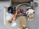
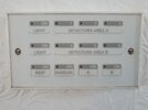
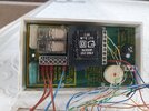
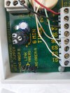
Thank you for the reply. Unfortunately I don't have any diagrams for the control unit as it was installed by the previous owner of my house. I do have a photo of the previous relay setup and the control panel.
The photo showing the inside of the control panel has a white terminal block label S1 to S6 these each S number references each pir which I have 4 in total, it also shows 12v out put.
 

Attachments

  • 20240830_135023.jpg
    20240830_135023.jpg
    3.1 MB · Views: 84
  • 20240903_080308.jpg
    20240903_080308.jpg
    2.4 MB · Views: 89
  • 20240811_110542.jpg
    20240811_110542.jpg
    3.2 MB · Views: 78
  • 20240811_110939.jpg
    20240811_110939.jpg
    1.6 MB · Views: 80
Assuming sensors and relay activate OK

This is how the added LIGHT should be wired to screw terminals on relay.

The left and right side of contacts may be reversed since NC is not used.


1725368756865.png


The wire colours if accurate are country specific.

1725369015726.png


1725369210824.png
 
Last edited:

Latest threads

New Articles From Microcontroller Tips

Back
Top