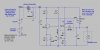
Here is a "protected" LDO regulator.
For reverse polarity input, I added a 2A fuse and a 3A silicon diode. In the simulation, you can see what happens to the output voltage V(out) just before the fuse blows. btw- almost all avionics and ham radio transceivers (Yaesu, Icom, Kenwood) all use this method of reverse polarity protection. If you are stupid enough to connect the car battery backwards, you deserve having to replace a fuse.
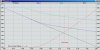
For positive excess voltage inputs, I added a zener diode and a signal diode. As the input voltage increases past the reverse conduction voltage of the Zener, current through it tricks the regulator into shutting down. Note that in the simulation, the input voltage is swept from 10V to 40V. You can see the saturation behavior from 10V to 12V, at which point V(vss) keeps climbing but V(out) stays at 12V (the regulation region). When V(Vss) exceeds about 15V, the Zener conducts, and the regulator shuts down, causing V(out) to go to zero. To show how that protects the PFET, I also plotted its power dissipation (black trace, in Watts).
The upper voltage limit in the positive direction is limited by the breakdown voltage on the 2N3904 and the PFET. If you think you are going to disconnect the car battery with the engine running, then you might want to get a higher voltage NPN in place of the 2n3904, and get a 100V PFEt. The 2n3904 is good to 40V.
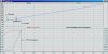
For reverse polarity input, I added a 2A fuse and a 3A silicon diode. In the simulation, you can see what happens to the output voltage V(out) just before the fuse blows. btw- almost all avionics and ham radio transceivers (Yaesu, Icom, Kenwood) all use this method of reverse polarity protection. If you are stupid enough to connect the car battery backwards, you deserve having to replace a fuse.
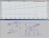
For positive excess voltage inputs, I added a zener diode and a signal diode. As the input voltage increases past the reverse conduction voltage of the Zener, current through it tricks the regulator into shutting down. Note that in the simulation, the input voltage is swept from 10V to 40V. You can see the saturation behavior from 10V to 12V, at which point V(vss) keeps climbing but V(out) stays at 12V (the regulation region). When V(Vss) exceeds about 15V, the Zener conducts, and the regulator shuts down, causing V(out) to go to zero. To show how that protects the PFET, I also plotted its power dissipation (black trace, in Watts).
The upper voltage limit in the positive direction is limited by the breakdown voltage on the 2N3904 and the PFET. If you think you are going to disconnect the car battery with the engine running, then you might want to get a higher voltage NPN in place of the 2n3904, and get a 100V PFEt. The 2n3904 is good to 40V.