Continue to Site

Welcome to our site!

Electro Tech is an online community (with over 170,000 members) who enjoy talking about and building electronic circuits, projects and gadgets. To participate you need to register. Registration is free. Click here to register now.

  • Welcome to our site! Electro Tech is an online community (with over 170,000 members) who enjoy talking about and building electronic circuits, projects and gadgets. To participate you need to register. Registration is free. Click here to register now.

Reading Data sheets BMP280

Status
Not open for further replies.

camerart

Well-Known Member
Hi,
I'm using a PIC to READ BMP280 DATA. This chip measures Temperature and pressure, for e,g, weather.
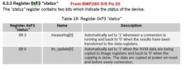
One of the registers is the STATUS reg, that has 2x BITs to check, '0' and '3'.
The D/S mentions the DATA registers, am I correct to think this means the BMP280 DATA registers?
Also 'The DATA are copied at power-on-reset and before every conversation. Does conversation mean when the chip is getting measurements, or sending to the PIC?
I'm puzzled about the exact timing of each of these BITs so if anyone can explain where these go in a program please.
I'm programming in BASIC, and if different programs use different timings, then just outline any information please.

Cheers. Camerart.
 

Attachments

  • STATUS.jpg
    STATUS.jpg
    71.8 KB · Views: 274
Have a look at the C++ code in the Arduino library, it's often far easier to understand that than to try and sort out information from the datasheet.
Hi N,
Thanks, but as I understand your CODE, it is for PIC, my question is for the BMP280 D/S, and when it is taking measurements, and able to be READ by the PIC which is an 18F46K20, and doesn't appear on your list. Once I figured it was for PICs I stopped reading so aplogies if it would have helped.
C
I didn't post any code, I suggested looking at the Arduino library - which is likely to be easier to understand than the datasheet - Arduino libraries are a great resource.

 
Have a look at the C++ code in the Arduino library, it's often far easier to understand that than to try and sort out information from the datasheet.
Hi N,
Thanks, but as I understand your CODE, it is for PIC, my question is for the BMP280 D/S, and when it is taking measurements, and able to be READ by the PIC which is an 18F46K20, and doesn't appear on your list. Once I figured it was for PICs I stopped reading so aplogies if it would have helped.
C
I didn't post any code, I suggested looking at the Arduino library - which is likely to be easier to understand than the datasheet - Arduino libraries are a great resource.

Hi N,
I clicked the link on your first reply, but now see it's on all of your replies. I now presume you mean find the Arduino libraries, is this correct? I looked through the CODE you posted, which looked promising, but I didn't see STATUS.0 or STATUS.3 anywhere.
C.
 
Hi N,
Thanks, but as I understand your CODE, it is for PIC, my question is for the BMP280 D/S, and when it is taking measurements, and able to be READ by the PIC which is an 18F46K20, and doesn't appear on your list. Once I figured it was for PICs I stopped reading so aplogies if it would have helped.
C

Hi N,
I clicked the link on your first reply, but now see it's on all of your replies. I now presume you mean find the Arduino libraries, is this correct? I looked through the CODE you posted, which looked promising, but I didn't see STATUS.0 or STATUS.3 anywhere.
C.
You should find what you need in the C++ libraries for Arduino, you need to convert it to run under BASIC on the PIC.

There's a routine that reads the status register?:

C++:
uint8_t Adafruit_BMP280::getStatus(void) {
  return read8(BMP280_REGISTER_STATUS);
}
 
You should find what you need in the C++ libraries for Arduino, you need to convert it to run under BASIC on the PIC.

There's a routine that reads the status register?:

C++:
uint8_t Adafruit_BMP280::getStatus(void) {
  return read8(BMP280_REGISTER_STATUS);
}
Hi N,
I can't read C++, although I saw that it read the STATUS register but couldn't see where the 2x BITs were mentioned. When I READ a BIT, I select one and define what I want the program to do with it. e,g, WHILE.
C.
 
Hi N,
I can't read C++, although I saw that it read the STATUS register but couldn't see where the 2x BITs were mentioned. When I READ a BIT, I select one and define what I want the program to do with it. e,g, WHILE.
C.

It's not that hard to read C++, just concentrate a little and you can make out roughly what it's doing, it's not that much different to modern BASIC. Using that in conjunction with the datasheet should help you work out what's going on.
 
It's not that hard to read C++, just concentrate a little and you can make out roughly what it's doing, it's not that much different to modern BASIC. Using that in conjunction with the datasheet should help you work out what's going on.
Hi N,
I've spent years concentrating on C and C++ and I'm afraid, as I'm more mechanical, and not so much a programmer, it bounces back out of my head so a waste of time.
Having said that I have scoured the net and found working CODE for this chip, that oinly mentions one of the BITs, I am trying to find out why in the D/S there are 2x BITs, and what the difference is between them.
Keep smiling, C.
 
Been having a quick look through the code, the status register is simply read in to a byte sized variable, and doesn't appear to be used in the examples that are given.

However, there is an unimplemented mention of 'forced mode'

C++:
/*!
 *  @brief  Take a new measurement (only possible in forced mode)
 *  !!!todo!!!
 */
/*
void Adafruit_BMP280::takeForcedMeasurement()
{
    // If we are in forced mode, the BME sensor goes back to sleep after each
    // measurement and we need to set it to forced mode once at this point, so
    // it will take the next measurement and then return to sleep again.
    // In normal mode simply does new measurements periodically.
    if (_measReg.mode == MODE_FORCED) {
        // set to forced mode, i.e. "take next measurement"
        write8(BMP280_REGISTER_CONTROL, _measReg.get());
        // wait until measurement has been completed, otherwise we would read
        // the values from the last measurement
        while (read8(BMP280_REGISTER_STATUS) & 0x08)
                delay(1);
    }
}
*/
Hi N,
Thanks, I also have been looking through Github and found this: https://github.com/BoschSensortec/BMP280_driver Which has given me some clues, and after talking a to a mate of mine, think we have the answer, until we find otherwise.

STATUS.0 is for when the PIC can READ the Compensation parameters, programmed by the manufacturers and STAUS.3 if for when the PIC can READ the DATA.
Let's see if he is correct.
Cheers, Camerart.
 
Hi C .. I dont 'know' this device (I am about to code for a BME280 module ), but your 'mate' looks about right. ie check the status.3 before any data reading and conversion..
 
Hi C .. I dont 'know' this device (I am about to code for a BME280 module ), but your 'mate' looks about right. ie check the status.3 before any data reading and conversion..
Hi G,
Some verification, great!
We were also trying to figure out STATUS.0 to, and after a little thought, I think that as READing I.D in the initialisation stage, seems reliable, then the chip will have had time to settle and be capable of the compensation DATA being READ also. I hope you agree?

The reason I went into all of this, is because I am getting an intermittent problem, in that at 'initialisation' I READ the ID, WRITE the set-up F4 and F5, then immediatelly READ them. sometimes the first READ is incorrect or correct.
Strangely, I have a kind of healing program from a week ago, that always READs, correctly, but I have moved on since then. So if I get a failure, then I program the 'healing' program first then the latest and it always works. This is a mystery. Let me know if you get anything like it please. Note: I've tried erasing, no difference!
C
 
Last edited:
Hi C .. I dont 'know' this device (I am about to code for a BME280 module ), but your 'mate' looks about right. ie check the status.3 before any data reading and conversion..
As I said above, that's only in 'forced mode' - in running mode it simply reads continually and you just need to read the data from it.

I presume 'forced mode' is a one shot reading?, and requires more work to use?. The Adafruit library appears to just use running mode.
 
Not got my module yet , but looking forward to sorting out the calibration / compensation routine .. also i've never used dsPIC33 SPI before ...( module has I2C ) Do I really need two decimal places ....
o_O:grumpy::banghead::nailbiting:

C:
// Returns temperature in DegC, resolution is 0.01 DegC. Output value of “5123” equals 51.23
DegC.
// t_fine carries fine temperature as global value
BME280_S32_t t_fine;
BME280_S32_t BME280_compensate_T_int32(BME280_S32_t adc_T)
{
BME280_S32_t var1, var2, T;
var1 = ((((adc_T>>3) – ((BME280_S32_t)dig_T1<<1))) * ((BME280_S32_t)dig_T2)) >> 11;
var2 = (((((adc_T>>4) – ((BME280_S32_t)dig_T1)) * ((adc_T>>4) – ((BME280_S32_t)dig_T1)))
>> 12) *
((BME280_S32_t)dig_T3)) >> 14;
t_fine = var1 + var2;
T = (t_fine * 5 + 128) >> 8;
return T;
}
( similar for pressure and RH..)
 
I've just used a BMP280 in the Round Clock project I showed on here recently. I can't comment on the code because I used an Arduino Nano and I don't understand PIC's ( or shovels for that matter :) );

I discovered there a 3 Modes ..

SLEEP .. which will only display data previously read;
FORCED .. will read & write but once only, then returning to SLEEP;
NORMAL .. which is made up of two parts .. ' t_***' which is read & write and then 't_standby' which is a variable pause before repeating the process continuously;

There is also a set of setup parameters to do with sampling, over-sampling, averaging, and the duration of measurement & standby time;

I found it difficult to get any consistent sense out of the module until I set those parameters.

As a novice, I have to say I probably achieved success partly by judgement but also with luck, so I'm no expert, but reading the comments above I do think you're missing something.


MM
 
Hi,
I was using PICs before Arduinos were introduced, and carried on using them..

The Arduino is a clever system for making things using libraries, and in a kind of LEGO way, much fatser to get results, but perhaps less knowledge learnt. Arduinos are microcomputers, with only slight differences from PIC e,g names etc. They tend to use boards with the Chip in the middle, where Pics, genrally use their own PCBs. I think they have the same manufacturer/owner.

I chose SPI over I2C, as I think it is more controllable, it uses 4 wires instead of 3.

If anyone would like to go through their set up and choses of F4 and F5 seetings, I'll be happy to go through it step by step, although I'm also learning, as always:0

I like to use an intitial in the reply,, so the person know who I'm 'talking' to, unless it's a general reply.

C.
 
C .. .

I was using PICs before Arduinos were introduced, and carried on using them..

I was not suggesting you should do anything but carry on using them.

The Arduino is a clever system for making things using libraries, and in a kind of LEGO way, much fatser to get results, but perhaps less knowledge learnt. Arduinos are microcomputers, with only slight differences from PIC e,g names etc. They tend to use boards with the Chip in the middle, where Pics, genrally use their own PCBs. I think they have the same manufacturer/owner.

There's not much of that I can agree with, but no matter.

I was just suggesting that the problems you highlighted at #13 are likely due to the 'set sampling' parameters in setup, as you will discover.


MM
 
C .. .


I was not suggesting you should do anything but carry on using them.


There's not much of that I can agree with, but no matter.

I was just suggesting that the problems you highlighted at #13 are likely due to the 'set sampling' parameters in setup, as you will discover.


MM
Hi M,
You seem defensive about my comments, nothing is meant by them.

Please explain your disagreements, so we can all understand where I may be going wrong.

Can you explain what may be wrong with my 'set sampling', so I can discover it earler please.

I suggested all working together, on the setups, which of course will be different, but we will better understand what's going on.

Cheers, C.
 
Status
Not open for further replies.

Latest threads

New Articles From Microcontroller Tips

Back
Top