Continue to Site

Welcome to our site!

Electro Tech is an online community (with over 170,000 members) who enjoy talking about and building electronic circuits, projects and gadgets. To participate you need to register. Registration is free. Click here to register now.

  • Welcome to our site! Electro Tech is an online community (with over 170,000 members) who enjoy talking about and building electronic circuits, projects and gadgets. To participate you need to register. Registration is free. Click here to register now.

Reading Data sheets BMP280

Status
Not open for further replies.
C ..
Please explain your disagreements, so we can all understand where I may be going wrong.

Your distain of Arduino is plain for all to see, but as I said, my disagreement is of no matter.

Can you explain what may be wrong with my 'set sampling', so I can discover it earlier please.

I suggested all working together, on the setups, which of course will be different, but we will better understand what's going on.

As I also said, I can't help with this because I don't understand the code and the parameters for your PIC will be quite different to my LEGO !

MM
 
C ..


Your distain of Arduino is plain for all to see, but as I said, my disagreement is of no matter.


As I also said, I can't help with this because I don't understand the code and the parameters for your PIC will be quite different to my LEGO !

MM
Hi M,
You have me all wrong! I've nothing against the Arduino system, all I meant is that it is modular.

I really I don't want any confrontation, only to get a program working.

If you see my comments as having any angle, then this only wastes time and energy.
C
 
m still learning :facepalm:.. Shovels i'm quite at home with..hole.jpg

Just to continue the thread drift...
The picture makes me think of Bernard Cribbins.

JimB
 
Hi M,
You have me all wrong! I've nothing against the Arduino system, all I meant is that it is modular.

I really I don't want any confrontation, only to get a program working.

If you see my comments as having any angle, then this only wastes time and energy.
C
That's the point of it :D

The main point is, a PIC is a processor, and an Arduino is a complete development board/system - there are plenty of PIC development boards are there, and the Arduino 'usually' uses an AVR processor. However, you can even get Arduino compatible boards with PIC processors on, that can be programmed from the Arduino IDE.

An interesting fact is that the Arduino was originally intended to have a PIC processor, but when MicroChip were approached they weren't interested in providing a compiler, Atmel were, so the AVR was chosen instead - the rest is history.

Both are simply tools for doing the same job, little to choose between them - the main advantage of the Arduino is the amazingly vast selection of examples and libraries out there, which are fairly easy to port to the PIC anyway.
 
Hi MM re your impressive 'LED clock' did the Arduino / BMP280 use SPI 3 or 4 wire . please. ( maybe I2c ).
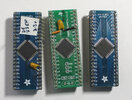
Hi C I did venture into Arduino world. but wasn't for me, as i was grappling ( still am ) with PICs and MPLABX and C I as a result now I fabricate various flavours (44 pin TQFP ) onto BOBs.. then drop them on to a breadboard to see if my ideas work . Having 37ish IO and PPS (pheripheral pin select) make this arrangement very flexible .
TQFP44.jpg


The picture makes me think of Bernard Cribbins.
Nearly right JimB ,my runner bean trench..
 
The modules I used only offered i2C connection; they are 3.3v and very vulnerable to 'noise'.
MM Many thanks, this BME280 module offers both at 5v, ( although the actual sensor device runs at 3.3v) i guess 3.3v can be more susceptible to noise , we shall see. my dsPICEV is a 5v device , i will probably use a screened cable to connect to mcu.
 
i will probably use a screened cable to connect to mcu.

I used screened cable for the sensors; I was told the typical audio screened cable can be quite 'lossy' so I used some fine screened satellite cable which had a foil screen, good results, but I also put a 10uf cap & a 104 ceramic across the 3.3v close to the module.

MM
 
Are you able to change the pull up resistors on the SDA, SCL I2C with arduino ? people have their own preference, ! but i found 2k2 works well me on 5v , not done many 3.3v over the many years. probably stuck to 2k2 as well. I see some designs use 4k7or higher if arduino is that high you could add / parallel a resistor somewhere.

Edit , I just answered my own question... I C that arduino I2C is just I/O no pull ups.
 
Last edited:
Are you able to change the pull up resistors on the SDA, SCL I2C with arduino ? people have their own preference, ! but i found 2k2 works well me on 5v , not done many 3.3v over the many years. probably stuck to 2k2 as well. I see some designs use 4k7or higher if arduino is that high you could add / parallel a resistor somewhere.

In my experience it makes VERY little difference what value you use (within reason), and with Arduino modules it's quite likely you've got a number of them paralleled as well, so probably lower than you think (if there's more than one module on the bus).
 
In my experience it makes VERY little difference what value you use (within reason), and with Arduino modules it's quite likely you've got a number of them paralleled as well, so probably lower than you think (if there's more than one module on the bus).

I found pull ups on Arduino i2C are a bit trial & error;
The i2C Bus on the Clock has a DS 3231, a BMP280 & a HTU 21F inline, but no pullups .. .. or problems;

I used an identical a sole DS 3231 on another project and 1k pullups were needed for function. The DS3231 module datasheet shows pullups along with a formula for calculating the resistance, but I always manage to get quite magical numbers with that process, so I tend to lick my thumb and hold it up, see how cold it gets ! :)

Not a lot of help, I'm afraid !

MM
I pick whichever resistors I happen to have to hand - if I recall correctly my PIC tutorials used 18K?. Unless you're using high speed mode it doesn't really matter.
 
Pretty well any Arduino I2C module has them, if not all of them?, as I mentioned in post #32 multiple modules means multiple resistors in parallel - generally it's only if you use a bare chip you don't get them.
 
I expect there are pages and pages of different opinions on the I2C pull up topic. as I am not using I2C libraries , and like to run at 400khz if possible I will scope the bus, and adjust resistors, settings ( slew rate ) etc. wire length is a consideration. also any pull up connected to a noisy Vcc is going to play its part.

I had a dabble with that conversion / calibration routine, and copied and pasted it from the pdf into MPLABX then after a few modifications i got a more or less good code. until i clicked 'build' ... XC16 didnt like two lines, and wanted a : after a ) ????
Took some time but this line and one below var1 = ((((adc_T>>3) - ((B ........ the character for - (minus) copied from the pdf wasn't a - (minus) at all . A delete of the offending character and a - press key sorted it ...

C:
BME280_S32_t BME280_compensate_T_int32(BME280_S32_t adc_T)
{
    BME280_S32_t var1, var2, T;
    var1 = ((((adc_T>>3) - ((BME280_S32_t)dig_T1<<1))) * ((BME280_S32_t)dig_T2)) >> 11;
    var2 = (((((adc_T>>4) - ((BME280_S32_t)dig_T1)) * ((adc_T>>4) - ((BME280_S32_t)dig_T1)))
    >> 12) * ((BME280_S32_t)dig_T3)) >> 14;
    t_fine = var1 + var2;
    T = (t_fine * 5 + 128) >> 8;
    return T;
}
 
Pretty well any Arduino I2C module has them, if not all of them?, as I mentioned in post #32 multiple modules means multiple resistors in parallel - generally it's only if you use a bare chip you don't get them.

Yes, you mentioned it. Thank you so much. Once was plenty.

And MM said there were no pullups in his system.
 
I expect there are pages and pages of different opinions on the I2C pull up topic. as I am not using I2C libraries , and like to run at 400khz if possible I will scope the bus, and adjust resistors, settings ( slew rate ) etc. wire length is a consideration. also any pull up connected to a noisy Vcc is going to play its part.
Why the need to run at 400KHz?, certainly for the device under discussion there's no point as it's a slow reading device. But certainly if you're wanting to push the spec. for faster devices then it's worth playing with.
 
Lest we forget.... The OP ISN'T using arduino.... He is using a PIC AND!!!! using basic not C or piggin C++

camerart .... This thread has gone tits up... Can we start again please.... The BMP280...

Has anyone answered your question?
 
Status
Not open for further replies.

New Articles From Microcontroller Tips

Back
Top