Continue to Site

Welcome to our site!

Electro Tech is an online community (with over 170,000 members) who enjoy talking about and building electronic circuits, projects and gadgets. To participate you need to register. Registration is free. Click here to register now.

  • Welcome to our site! Electro Tech is an online community (with over 170,000 members) who enjoy talking about and building electronic circuits, projects and gadgets. To participate you need to register. Registration is free. Click here to register now.

Ramp Generator...How would you do it?

Status
Not open for further replies.

KMoffett

Well-Known Member
This is a project for which I've worked out a solution...it works on the breadboard. But, I wonder how others might have solved it. This is a signal source for one of our Physics Prof's demos. And no, I'm not a student. :)

His requirements:
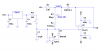
Analog ramp generator (no steps)
+5.00V to 0.00V down ramp
30 second period
One ramp per button push
Drive a 10K control-voltage input on a sweep function generator
Battery powered
Simple (my requirement) ;)

I'll post my schematic later.

Ken
 
You want linear, or is a segment of RC discharge curve ok?
 
Last edited:
I'd use a constant current source, with a fixed open circuit voltage of 5V, plus a capacitor.

Connect it to an inverting amplifier biased at 2.5V.

D1 plus I1 symbolise the current source, obviously the actual current will need to be calibrated to match C1 (which should be low leakage tantalum) and account for its leakage.
 

Attachments

  • Ramp1.GIF
    Ramp1.GIF
    3.5 KB · Views: 568
Mike,
He wants "linear".

Hero,
Even with "rail-to-rail" op amps you will not get to "0.00V". Getting a descending ramp to 0.00 V has been the major challenge.

Ken
 
Last edited:
...
Even with "rail-to-rail" op amps you will not get to "0.00V". Getting a descending ramp to 0.00 V has been the major challenge.

Not if you are willing to use a negative rail on the op-amp. Since the load is a 10K resistor to ground, I would suggest that a CMOS rail-to-rail-output opamp operated off only a positive rail would do just fine.

A variant **broken link removed** that inverts the output should do it.
 
Last edited:
Hero,
Even with "rail-to-rail" op amps you will not get to "0.00V". Getting a descending ramp to 0.00 V has been the major challenge.
You get as near as damn it 0V, at least to two decimal places.

Assuming the signal generator's input looks like a 10k resistor connected to 0V, zero voltage won't be the problem, 5V will, so run the op-amps from a higher voltage e.g. a 9V battery would solve the problem as well as eliminate the need for rail-to-rail op-amps.

Why not have a digital solution?

If you use enough bits and an anti aliasing filter the steps won't be noticeable, a 10-bit DAC will give <5mV resolution.

I'd use a CD4040, an R2R DAC and a CD4069.

The 4040 is 14-bit counter which will give a step of just over 305µV

Two of the gates from the CD4069 would be used as a clock for the C4040, the remainder would be configured as a linear amplifier with unity gain both buffer and invert the signal and should have a low enough impedance.

If the CD4069 isn't linear enough, I'd use a dual rail-to-rail op-amp IC with one configured as a Schmitt trigger oscillator and the other as an inverting buffer.

A diode AND gate could disable the counter when finished.
 
Mike,
A -supply is OK. But, an you suggest an appropriate op amp for a single supply?

ken
 
The LM358 would work.

I think the digital solution is probably the best.
 
I've just reread your previous post and still don't see what you're getting at. The LM358 will work providing the supply voltage is >6.5V.
 
I added the link to a circuit which generates a positive-slope linear ramp off a single 5V supply. Inverting the output would satisfy Ken's requirement.
 
Last edited:
Sorry, I didn't realise that remark was directed at Ken, even though it should have been obvious from the quote.
 
Mike and Hero,

OK, here's what I had put together after trying several different approaches. It's more involved than I had originally hoped. That's why I was hoping for a really simple approach that I had overlooked.

The output will ramp down from +5.000V to -0.002V in 29.5 seconds. Good enough for government work. ;)

The precision half-wave rectifier gave me the best zero-voltage out result. With the SW1 closed R6 is adjusted to +5.000 on the output.

Thanks for the input. :)

Ken
 

Attachments

  • 5V-0V-30SecRampGenerator2A.gif
    5V-0V-30SecRampGenerator2A.gif
    26.4 KB · Views: 2,100
Yes, that would be a way to do it. The Prof was using another function generator as a ramp source for the swept function generator. But, he wanted this so he wouldn't have to go to all the trouble for setting that one up to those specific parameters each time. :)

Ken
 
Ken, I like that approach. Attached is what my first cut might look like. I simulated it. I haven't built it.
 

Attachments

  • 30 second ramp sch.PNG
    30 second ramp sch.PNG
    31.3 KB · Views: 293
Last edited:
Status
Not open for further replies.

Latest threads

New Articles From Microcontroller Tips

Back
Top