Continue to Site

Welcome to our site!

Electro Tech is an online community (with over 170,000 members) who enjoy talking about and building electronic circuits, projects and gadgets. To participate you need to register. Registration is free. Click here to register now.

  • Welcome to our site! Electro Tech is an online community (with over 170,000 members) who enjoy talking about and building electronic circuits, projects and gadgets. To participate you need to register. Registration is free. Click here to register now.

Radial leaded Electrolytic capacitor lifetime equations

Status
Not open for further replies.

Flyback

Well-Known Member
Hello,

Long post, but please only skim read and I beg you to shovel any answer you think may have any relevance whatsoever (even if it doesn’t) , to this horrendous subject of pinning down the actual lifetime of radial leaded electrolytic capacitors………

Our investors want us to write them a report on the lifetime of “Wet” Aluminium Electrolytic Capacitors in our product. (60W offline flyback, 110-265VAC input)

The electroytic capacitor we are using is the Acon KL series 400V, 100uF one. (as attached)
This is the capacitor that our Chinese designers put in our product. (Post rectifier capacitor)

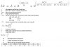
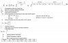
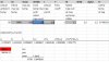
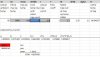
The Chinese designers sent us the attached lifetime calculation for this capacitor.
The strange thing is, in this formula, if one decreases the ripple current value flowing in the capacitor, then the lifetime decreases!!!....
(This is from one of the bigegst SMPS designers in China...they make SMPS for most of the western world.)

….This can’t be right, does anyone know what’s gone wrong here? And is there any other formulae for radial leaded electrolytic capacitors lifetime?
As you can see, the Chinese capacitor lifetime equation lists a parameter called “delta(Tj0)”…
This parameter is the “internal temperature rise when rated ripple current is applied”.
Strangely, they don’t tell us what this value [“delta(Tj0)”] is for the Acon KL series capacitor…..instead, their lifetime equation simply gives “delta(Tj0)” values for the Rubycon USR, USC & USG series capacitors. –But that’s not what we are using, so why do they state it?

Also, another parameter used in the attached lifetime equation is called “alpha”. It is the “ratio of the case top and core of the capacitor element”. From the attached lifetime exerpt, you can see that the lower the diameter of the capacitor body, the greater the temperature of the capacitor case gets. Is this typical for other electrolytic capacitors too?...it doesn’t seem to make sense…..because surely the deciding factor is how long the capacitor body is?....that is, longer body capacitors would run hotter as its further from the internals to the base…the base being where most heat transfers out of the capacitor?

Anyway, why does our Chinese designers lifetime equation give a lower lifetime when the capacitor has less ripple current in it? Have I missed something?

Also, why does no radial electrolytic capacitor manufacturer give thermal resistance values from internal core to the case for their capacitors?..it is impossible to actually do a lifetime calculation without this information.
 

Attachments

  • Electrolytic capacitor lifetime.jpg
    Electrolytic capacitor lifetime.jpg
    90.6 KB · Views: 177
  • Acon KL capacitor.pdf
    89.1 KB · Views: 199
The main equation has got L, the lifetime, and Lb, the basic lifetime, the wrong way round. The other equations look to me as though they work the correct way, but one is written the opposite way round from what looks logical to me, even though it is mathematically correct.

Also the explanations of some of the temperature terms are misleading.

And there is a ΔIj that seems to make sense if it is ΔTj

The equation for the temperature rise due to ripple current is ΔTj = ΔTj0 x (I/F/I0)^2
which seems quite straight forward. ΔTj0, the rated temperature rise, is quoted for the different capacitor types, as is I0, the rated ripple current and F, the factor for the frequency of the ripple. That also makes sense that the temperature rise is proportional to the square of the ripple current.

ΔTj is then used in Ta = Tc - ΔTj/α

For this to work, you have to assume that they mean ΔTj not the ΔIj that it looks like on the image. As neither Ij nor ΔIj are used anywhere else, I think that ΔTj, which was calculated in the line above is what is meant.

Then Ta is defined as "Calculated Ambient Temperature", but further up the page it is "Actual Ambient Temperature", and it is only used in this one place. I think it means "Ambient Temperature" and whether you measure it or calculate it for your application, it is an input to the capacitor life calculation, not an output.

Tc is defined as "Surface temperature of capacitor", and it is used in the equation at the top of the page. That is the output of Ta = Tc - ΔTj/α, and I have no idea why they wrote it that way round. Writing it the obvious way round (to my way of thinking) it becomes:-
Tc = Ta + ΔTj/α
which also makes sense, in that the surface temperature you need to calculate for the other equations comes from the ambient temperature plus a factor proportional to the square of the ripple current, and inversely proportional to "α", which gets slightly larger with larger capacitors.

I don't quite see why doubling the ripple current would only increase the temperature rise by a factor of 4/1.6 = 2.5 on a 35 mm diameter capacitor, but by a factor of 4 on a 10 mm capacitor, but it's their call. All of these temperature rises are based on their starting values of ΔTj0, so I would assume that they know what they are talking about.

When you have Tc and ΔTj, you can put them into the equation at the top, along with Tmax and ΔTj0.

They have got Lb and L the wrong way round. If you have a look at **broken link removed** that shows a similar equation for temperature, but with a different way of dealing with the self-heating. That show the correct way round, as it is obvious that the life will increase with decreasing temperature. If it went the other way, those capacitors would have a life of less than a day at 20 °C and no ripple, so they would be dead before you got them.

Neither the formula you showed nor the one in the link have a term for supply voltage. I have seen voltage terms where the life is inversely proportional to voltage, so near infinite at 0 V, and another where the life is linearly related to voltage, and about 2.5 times at half voltage and 4 times at zero voltage. I would have expected some life increase at reduced voltage.
 
Last edited:
Thanks very much Diver300, you're right, they got "L" and "Lb" the wrong way round.
Diver300 you are fab!
You have corrected everything here.
The only thing about the equation is that they have used "2^[(Tmax - Tc)/10]", instead of the term that most other manufacturers use , which is "2^[(Tmax - Ta)/10]"

where...
Ta = ambinet temperature
Tc = Case surface temperature
Tmax = Max allowable ambient temperature (when max rated ripple is flowing).

Do you know which version of this expression is correct?

Also , they have not said how they calculate "delta_Tj0", this is the internal temp rise when rated ripple current is flowing.

Do you know how they calculate "delta_Tj0"?
 
Last edited:
Also, if i put in 0.001A for ripple current in your kindly corrected equation, (at 85degC ambient) then i get a lifetime of just 3.4 years....this seems a bit low for a capacitor with virtually no ripple current in it. Can this be right?
 
The ripple current term is the least important. I have no idea whether that is right or not, as it has far less effect than the temperature component. The mistake was obvious because both corrections were in the wrong direction.

Tc and Ta will not be far apart. I don't know why this formula adds a bit to Tc and has another term using ΔTj as well. Also the calculation uses 3 different base valued for temperature rise (10, 5 and 3.5 °C) instead of a thermal resistance. I don't know why, but I doubt it makes any real difference compared to other ripple current corrections.

3.4 years at 85 °C sounds about right. Temperature has the biggest effect on the life, and no ripple current just means no extra heating, but with an ambient of 85 °C, that is hot enough already.
 
Hello,

I have another problem with a Electrolytic capacitor lifetime equation provided by a different manufacturer…this time Rubycon….
So, I am also trying to do a lifetime equation for the Rubycon TXW, 450V, 100uF Radial Leaded Electrolytic capacitor.
(ripple current (I) = 0.54Arms; Ambient temp = 85degC)

However, the lifetime equation provided by Rubycon (linked below) is giving garbage numbers.
Rubycon capacitor lifetime equation…..(equation 4.7)….
**broken link removed**

When you make out an excel spreadsheet for equation 4.7, then if you reduce the ripple current in the capacitor (I), then the lifetime reduces!!!...this makes no sense.

Do you know what’s going on?
I have provided here (attached) my Excel spreadsheet of the equation 4.7...(woops , no i havent, it wont let me upload the excel)

Rubycon TXW series datasheet (100uF, 450V capacitor)
**broken link removed**

The equation 4.7 seems to give better numbers when a really low ESR is used. (say less than 0.1 ohms). However, the ESR of the 100uF, 450V capacitor is 3.32 ohms at 120Hz…..this high value of ESR gives nonsense values for lifetime.

Even with sub 0.1 ohm values of ESR, the lifetime equation gives out silly numbes for lifetime…..for example, when you put a really low value of ripple current in, the lifetime hardly reduces at all.

It just doesn’t make sense?
Do you know a proper Rubycon capacitor lifetime equation?

The equation 4.7 is said to NOT work at all for delta_Tj values above 20……this is ridiculous as that’s exactly where it calculates out to.

(it wont let me upload the excel calculation document)
 
Last edited:
Also the calculation uses 3 different base valued for temperature rise (10, 5 and 3.5 °C) instead of a thermal resistance.
Thanks, after years of looking, i have never seen a thermal resistance value for any electrolytic capacitor...do you know why its never given?
 
I don't know why this formula adds a bit to Tc
Thanks, but isnt it so that the case would be a bit hotter than the ambient temperature? (if there is ripple current flowing in the capacitor)
 
Last edited:
Also, the first page of the rubycon document..given again here...
**broken link removed**
...states that capacitor surface temperature should be measured at the top of the case....i always thought it should be the bottom of the case?
 
Hello,
woops , corrected second term of lifetime equation attached
 

Attachments

  • Ripple decreases life of electrolytic.jpg
    Ripple decreases life of electrolytic.jpg
    218.6 KB · Views: 116
Last edited:
Also, the Electrolytic capacitor lifetime equation in post #1 above is from a document that concerns the Akon KL series Radial Electrolytic capacitor. So therefore, why , in the exerpt shown in post #1, do they give “delta_Tj0” example figures from the Rubycon "snap-in" series capacitors? (USR, USG, USC & VXP)

"Snap-in" capacitors endure far less internal temperature rise than Radial Electrolytics, so therefore why have they not given temperature rise figures for Radial Electrolytics?.......After all, in the SMPS that they designed for us, they put in a Radial Electrolytic, ...the Akon KL series.

As you know, “delta_Tj0” is the internal temperature rise of the capacitor which happens when rated ripple current is flowing in the capacitor.
 
Can you confirm that the load life quoted at the top of an electrolytic capacitor datasheet, is simply the life with zero ripple current in it, at the maximum ambient temperature?

Eg for the Rubycon BXC series datasheet, it would last 8000 hours if stored at 105 degC....(obviously with zero ripple current in it).

Rubycon BXC series datasheet
https://www.rubycon.co.jp/en/catalog/...inum/e_bxc.pdf
 
Hello,

This is related to the above so please may i put it here if its ok, though it is a separate new post

Attached is the equation for electrolytic capacitor lifetime.
It was provided to us by our Chinese SMPS designer.
According to this equation, as delta_Tj0 increases, so too does lifetime.
That doesn’t make sense…..if the internals were getting hotter, then lifetime should get less.
Can you say that this equation is incorrect?
 

Attachments

  • Electrolytic lifetime equation.jpg
    Electrolytic lifetime equation.jpg
    98.7 KB · Views: 181
Hello,
This is related to the above so please may i put it here?...

Page 16 of this Panasonic document gives an overly simplistic equation for electrolytic capacitor lifetime calculation….

Panasonic electrolytic capacitor app note...
**broken link removed**

I actually used to work for Panasonic. We used to make consumer goods branded Panasonic. We used to use all Panasonic’s own electrolytic capacitors in the products we made. We used to have full-featured lifetime equations for each family of Panasonic electrolytic capacitors. These were provided by the Panasonic management. However, Panasonic do not make these equations public. Why not?

Do you agree that really getting to the bottom of electrolytic capacitor lifetime, for any individual family of radial leaded electrolytic capacitors is impossible?

After all, the big companies that make these electrolytic capacitors probably have allegiances to big electronics companies who demand that full featured lifetime equations are kept secret?
Do you agree?
 
Cribbed from Wikipedia:

"Lies, damned lies, and statistics" is a phrase describing the persuasive power of numbers, particularly the use of statistics to bolster weak arguments. It is also sometimes colloquially used to doubt statistics used to prove an opponent's point.

The term was popularised in United States by Mark Twain (among others), who attributed it to the British Prime Minister Benjamin Disraeli: "There are three kinds of lies: lies, damned lies, and statistics." However, the phrase is not found in any of Disraeli's works and the earliest known appearances were years after his death. Several other people have been listed as originators of the quote, and it is often erroneously attributed to Twain himself.

To this we could also add MTBF calculations and capacitor lifetime calculations.

In a past life I have done MTBF calculations as per Mil HDBK 217, in order to satisfy the requirements of a "demanding" client.

I have never done capacitor like calculations.

My best guess is that the equations produced by the capacitor manufacturers are there to give a rough indication of the expected life in response to varying service conditions.
Why there are apparent errors in the equations given by the various manufacturers I do not know. Maybe it was a job given to a "Holiday Student", ie someone on their summer break from university who is getting in a bit of industrial experience.

Do you agree that really getting to the bottom of electrolytic capacitor lifetime, for any individual family of radial leaded electrolytic capacitors is impossible?
Yes.

If you get a million of the capacitors and run then under defined conditions until most of them are "dead", and then average out the lifetime of the ones that died, you will get an average lifetime.
But, some will have died after 6 months, some will last over 10 years.
That is how Damned Lies statistics work.

JimB
 
Hello,

This is related to the above so please may i put it here if its ok, though it is a separate new post

Attached is the equation for electrolytic capacitor lifetime.
It was provided to us by our Chinese SMPS designer.
According to this equation, as delta_Tj0 increases, so too does lifetime.
That doesn’t make sense…..if the internals were getting hotter, then lifetime should get less.
Can you say that this equation is incorrect?

The point about ΔTj0 is that it is the baseline that the capacitor is rated at. It can't be changed by changing how the capacitor is run. What changes is ΔTj if the capacitor is subjected to different conditions. The explanation on the equation says:-
"ΔTj0 : Internal temperature rise when maximum rated ripple current is applied."
So the Acon 100 μF, 400 V capacitor lifetime is rated at 5000 hours at 105 °C and 610 mA ripple at 120 Hz

The ripple current term is 2^(ΔTj0/(10-0.25*ΔTj0)-ΔTj/(10-0.25*ΔTj)).

ΔTj is calculated as ΔTj0 * (I / F / I0)^2

I think that ΔTj0 is 10 °C

If the ripple current were half as much, 305 mA, and the frequency is still 120 Hz, then ΔTj would be 2.5 °C

ΔTj0/(10-0.25*ΔTj0) is 10/7.5 = 1.33333
and ΔTj/(10-0.25*ΔTj)) is 2.5/9.375 = 0.266666
so ΔTj0/(10-0.25*ΔTj0)-ΔTj/(10-0.25*ΔTj) is 1.3333 - 0.266666 = 1.066666
and 2^(ΔTj0/(10-0.25*ΔTj0)-ΔTj/(10-0.25*ΔTj)) is 2^1.066666 = 2.095

So halving the ripple current increases the life by just over 2 times.
 
Thanks, the thing is, supposing you have two electrolytic caps which are basically the same, except one has 10 degrees internal temp rise with full rated ripple, and the other has 5 degrees temp rise with full rated ripple current…...
……well then you would expect the one with just 5 degrees temp rise to be longer lasting….but that does not happen…..the attached excel sheets proove this…..if you put in the lower temp rise in the blue square you see the lifetime decrease, which doesnt make sense.
I think the equation is wrong. Surely?

The attached exel uses the equation given in post #13...you can see from the blue and red squares in the attached here.
 

Attachments

  • Excel lifetme calculation      _delta_Tj0 is 10 degrees.jpg
    Excel lifetme calculation _delta_Tj0 is 10 degrees.jpg
    71 KB · Views: 129
  • Excel lifetme calculation      _delta_Tj0 is 5 degrees.jpg
    Excel lifetme calculation _delta_Tj0 is 5 degrees.jpg
    68.2 KB · Views: 114
Thanks, the thing is, supposing you have two electrolytic caps which are basically the same, except one has 10 degrees internal temp rise with full rated ripple, and the other has 5 degrees temp rise with full rated ripple current…...
……well then you would expect the one with just 5 degrees temp rise to be longer lasting…
No, I wouldn't.

The one with the 10 ° rise is rated to the 8000 hours with that 10 ° rise, so it is effectively rated to run at 95 °C internally for 8000 hour. When you halve the ripple current, the temperature rise is 1/4 as much, so the internal temperature is around 87.5 °C, or 7.5 ° cooler than its rating.

The one with the 5 ° rise is rated to the 8000 hours with that 5 ° rise, so 90 °C internally for 8000 hour. When you halve the ripple current, the temperature rise is 1/4 as much, so the internal temperature is around 86.25 °C, or 3.75 ° cooler than its rating.

So the one that has the larger temperature margin below its rating will last longest. The one with a 5 ° rise has been made less tolerant of temperature, because a lower temperature is expected.
 
Status
Not open for further replies.

Latest threads

New Articles From Microcontroller Tips

Back
Top