Continue to Site

Welcome to our site!

Electro Tech is an online community (with over 170,000 members) who enjoy talking about and building electronic circuits, projects and gadgets. To participate you need to register. Registration is free. Click here to register now.

  • Welcome to our site! Electro Tech is an online community (with over 170,000 members) who enjoy talking about and building electronic circuits, projects and gadgets. To participate you need to register. Registration is free. Click here to register now.

quick simple schematic check, please...

Status
Not open for further replies.
oh, i see. so... like this?
240-l_0813957a85a24264bf43e4907707eedc.jpg

i wasn't sure whether to put the pot before or after the 15ohm resistor (or if that even matters). just saying.
 
Now when the pot increases the current then all or most of the LEDs will burn out.
Each string must have its own current limiting resistor.
 
Most pots are rated at 1/2W over the entire resistance. When it is turned to half then only half of the resistance is heating and its rating becomes 1/4W max. When it is turned so that only 10% of its resistance is used then the current is almost maximum and only 10% of the resistance is heating a lot with only a 1/20W rating.

What? Can you show a reference to this? This is totally different from anything I've ever heard about a pot. A pot is rated by by it's wattage over it's whole range, not a portion of it. A 1/2W pot is a 1/2W no matter where it's adjusted.
 
The entire resistance element of a pot has its power rated. Half of the resistance has half of the power rating. 1/10th of the resistance has 1/10th of its total power rating.
A pot is designed to be a voltage divider, not a power rheostat.
 
OK, I know this is a little off topic from this thread and I’m not trying to belabor this discussion or nitpick anyone’s comments, but I’ve been grinding my gears about the pot burning out issue. I am not a EE by education so I feel like I’m at a little bit of a disadvantage here sometimes and I have a few questions that might be really basic.

To help me understand the problems with using a pot the way I proposed, I came up with some equations and graphed the results. If I’ve made any errors in any of the steps please let me know. Here’s what I did.

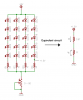
I took the OP’s circuit and replaced it with an equivalent circuit just to make the analysis easier:

247-38297d1264721716-quick-simple-schematic-check-please-pot-power.png


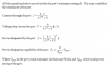
Then I wrote the equations for current through the circuit, voltage drop across the pot, power dissipated by the pot, and lastly the power dissipation capability of the pot all with respect to its resistance setting.

From an earlier post I got the impression that the power dissipation capability was linearly proportional to the resistance setting. When the pot is at its full resistance, the power dissipation capability is whatever it’s rated for, when it is at or near zero resistance, its power dissipation capability is at or near zero. Here are the equations:

248-38298d1264721720-quick-simple-schematic-check-please-pot-power-equations.png


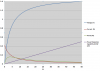
Next, I plugged the equations into an excel spreadsheet so I could see what was going on. In viewing the graphs the power dissipated by the pot never even gets up to 200 mW but there is a region from about 0 - 11Ω where the pot is set to low resistance that the power being dissipated exceeds its power dissipation capability. That I assume is what adiouguru referring to.

249-38302d1264723595-quick-simple-schematic-check-please-pot-graph-1.png

I can see this now and it makes sense. This region exists because the power dissipation capability increases linearly while the power being dissipated increases exponentially. As a result, there will always be a region where the pot resistance setting is low that you have insufficient power dissipation capability.

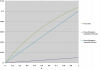
The higher the power rating of the pot and the lower the initial current, the smaller that region will be but it will always be there. Here is another graph with a line corresponding to the power dissipation capability of a 1/2W pot and one for a 5W pot. It's zoomed in to show the effect but even with the 5W pot the region still exists.

250-38303d1264723595-quick-simple-schematic-check-please-pot-graph-2.png

And, if I understand all this correctly, that region will exist anytime you use a pot regardless of the specific circuit, voltages, or currents involved.

So my questions are what’s the breaking point? How do you know when this region will be problematic and when won’t it? I have used pots in many circuit and have never considered this and so far to my knowledge it hasn’t bit me in the you know what and I don’t want it to. How do I know when this effect will be a problem and when it will not?

Thank you in advance for the explainations.
 

Attachments

  • pot power.PNG
    pot power.PNG
    17.1 KB · Views: 132
  • Pot power equations.PNG
    Pot power equations.PNG
    18.1 KB · Views: 138
  • pot graph 1.PNG
    pot graph 1.PNG
    77.3 KB · Views: 126
  • pot graph 2.PNG
    pot graph 2.PNG
    74.4 KB · Views: 124
Last edited:
If you're dead set on using a POT, or at least something like it, use a rotary switch to switch several banks of LEDs, it's simple it's efficient and it only requires you to find a rotary switch that can conduct the current required, which isn't very high.
 
My stereo speakers have a rheostat variable power resistor in series with the tweeters to balance the highs and lows. The rheostat is rated at 5W and has burned out because it is always set to near max where only a small part of the resistance is in series with the tweeter and it burns up.
I replaced both burned rheostats and the replacements have also burned out.
 
If you're dead set on using a POT, or at least something like it, use a rotary switch to switch several banks of LEDs, it's simple it's efficient and it only requires you to find a rotary switch that can conduct the current required, which isn't very high.

I'm not dead set on using a pot. I don't even want to use a pot. If I was building this circuit I would use PWM to dim. I just wanted to make sure I understood the effect that audioguru was speaking of. Plus I like doing math and making fancy graphs.:D

My stereo speakers have a rheostat variable power resistor in series with the tweeters to balance the highs and lows. The rheostat is rated at 5W and has burned out because it is always set to near max where only a small part of the resistance is in series with the tweeter and it burns up.
I replaced both burned rheostats and the replacements have also burned out.

So basically, one should avoid having a pot turned down to near zero resistance in any circuit if at all possible. Would you agree with that statement?
 
In any power circuit sure, not in signal circuits, power dissipation shouldn't be a problem in signal circuits. The effects of a POT near it's lowest resistance state can be eliminated by putting an additional resistor in series with it, static power resistors are cheaper and common, but it in your case it would limit the minimum possible brightness, IE you wouldn't be able to dim it to 0. But you wouldn't want to anyways as that's pointlessly wasting the battery on a flashlight thats supposed to be 'off'.
 
Last edited:
The effects of a POT near it's lowest resistance state can be eliminated by putting an additional resistor in series with it

I don't think I understand that. I mean, that's the exact circuit that I used in post #25 and was told it would burn out the pot. I can see how placing a resistor in series would limit the maximum current going through the pot and so that region of insufficient power dissipation near zero resistance would be smaller, but it would still be there. I guess like with almost any circuit it's just a matter of the currents involved. Hence your statement about not having to worry about the effect with signal circuits, I assume becasue of the relatively low currents. I was hoping there was some rule of thumb or something that could help me judge when I should worry about it and when it was OK. It doesn't sound like it though.

Let me ask this, why is it OK to use the pot in the 317 current source circuit shown above? The currents will be just as bad. Shouldn't there be the same concern about the pot burning out? Right now with the 15Ω resistor the max current he will get out of he 317 is about 83 mA which is only ~ 20% what he needs. But, if he were to decrease the 15Ω resistor to a ~3Ω resistor that would allow the 317 to provide the 400mA his LEDs require for full brightness but then the pot would be just as bad off. Am I missing something? Thanks for the responses.
 
Yes, the pot will also burn out with an LM317 adjustable current regulator. Use a switch and some resistors that are big enough to dissipate the heat.
 
A 500 ohm wire wound pot is cheap and a commonly available item. That would work fine with the LM317 and 15 ohm resistor.

Personally I think continuously variable brightness on a lantern is dumb, I would prefer 2 or 3 brightness settings, maybe implemented as a 4 position rotary switch;
off - low - med - high.
 
Oh no! Conflicting information! What should I do!?! AHHHHH!!! Just kidding. Hey guys I'm just going to test it. I have all these parts lying around and I don't mind frying a pot just to see what happens. I got enough magic smoke to go around! :D
 
Last edited:
You'd have to work the math out, a simulator preferred, but even with a limited power output POT you can chose an appropriate static power resistor to use in series with it which will help dramatically compared to the cost of a higher power POT. It's still 100% waste of the energy and the series resistor limits the minimum brightness, but for a flashlight this is not a bad thing. For even moderately controllable lighting I'd recommend a 555 circuit driving a single bank, but if you have a bunch of junk low current switches floating around switching banks in binary fashion with a few SPST switches is a quick and easy solution.
 
Last edited:
Mr RB:
well the "wire wound pot" idea sounds easy enough, but it kinda seems like there's a lot of conflict around the whole using-a-pot idea (judging by everyone's else's responses). i mean i'd be glad to do that, but with Audioguru (and whoever else) saying not to use a pot... im not sure what to do now :/
but your other suggestion to use brightness settings using a rotary switch would be totally fine. i'd have no problem using that instead of the fine-tuned brightness control i initially had in mind, except that it seems a lot more confusing and complicated. like im mainly just confused on where i'd connect evverything. for example, on **broken link removed** 4 position switch there are 18 terminals, and i have to admit, that's a little intimidating for me ._. (btw, if i decide to use the rotary switch, would i still be using the LM317 too?)
 
Last edited:
Buy a switch that has a detailed datasheet so you can see which terminal does things.
The switch with 18 terminals does not have a datasheet so you are just guessing.
 
Mr RB:
well the "wire wound pot" idea sounds easy enough, but it kinda seems like there's a lot of conflict around the whole using-a-pot idea (judging by everyone's else's responses). i mean i'd be glad to do that, but with Audioguru (and whoever else) saying not to use a pot... im not sure what to do now :/
but your other suggestion to use brightness settings using a rotary switch would be totally fine. i'd have no problem using that instead of the fine-tuned brightness control i initially had in mind, except that it seems a lot more confusing and complicated. like im mainly just confused on where i'd connect evverything. for example, on **broken link removed** 4 position switch there are 18 terminals, and i have to admit, that's a little intimidating for me ._. (btw, if i decide to use the rotary switch, would i still be using the LM317 too?)

Using a rotary switch is a simple solution if you are OK with not having continuos brightness adjustment which it sounds like you are. Here is an example of a switch that would work for you. Click on the link to the data sheet for information on which pins correspond to which positions. It has 4 posititions so you will have 4 brightness levels. You can select a switch with more positions if you want additional brightness levels. The attached schematic shows one way you can wire up resistors to adjust the brightness. You don't need the 317. That was just when you were going to use it as an adjustable current source.

LED_rotary_switch.PNG
 
Never buy a switch that has listed, "switching pattern unknown" and does not have a datasheet.
 
Mr RB:
well the "wire wound pot" idea sounds easy enough, but it kinda seems like there's a lot of conflict around the whole using-a-pot idea (judging by everyone's else's responses). i mean i'd be glad to do that, but with Audioguru (and whoever else) saying not to use a pot... im not sure what to do now :/
...

You can use a wire wound pot and a 15 ohm resistor (in series) and use them as the current sense resistor in the LM317 design. It won't "waste power" in the pot because the LM317 will always make 1.2v over that resistor whther it is a pot or some other resistor.

With the 15ohm resistor it limits the max current to about 80mA and with the pot turned right down you get about 515 ohms which will be about 2.3mA.

Total parts LM317, 500 ohm wire-wound pot, 15 ohm resistor, 12v battery (and your 20 LEDs).

There are heaps of good suggestions on how to do it, this is only one way. I think you should just jump in and get some parts and wire it up using the circuit of your choice, you could have had it built in 15 minutes. ;)
 
oh, cool. alright, so i got a good idea of what to do now. and im probably going to end up using the rotary switch idea.
so thanks for all your help. i really appreciate it. :D
 
Status
Not open for further replies.

Latest threads

New Articles From Microcontroller Tips

Back
Top