Continue to Site

Welcome to our site!

Electro Tech is an online community (with over 170,000 members) who enjoy talking about and building electronic circuits, projects and gadgets. To participate you need to register. Registration is free. Click here to register now.

  • Welcome to our site! Electro Tech is an online community (with over 170,000 members) who enjoy talking about and building electronic circuits, projects and gadgets. To participate you need to register. Registration is free. Click here to register now.

Question RE: NE555 pulse generator

Status
Not open for further replies.

dwhitt

New Member
Question RE: NE555 pulse generator **added schematic**

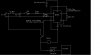
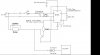
I have a circuit using the NE555 wired in the typical astable operation. I am using ~6.1V input (Vdd). However my ouptput square wave is measuring 3.2V. I need the ouput square wave to be at least 5V.

What is causing this and what can I do to correct this problem?

FWIW I also tried using ~12V input but I kept burning up chips. It seems to work fine with the lower volate but I am getting the unwanted voltage drop.

Thanks in advance.
 
Last edited:
You probably have the output overloaded. Post a schematic of your whole circuit.
 
Thanks. I only have a hand drawn one at the moment but will try to come up with something to post before I leave today.
 
See if this works. I did this quickly and please keep in mind that drawing electrical schematics are not part of my job so forgive me if I got a symbol wrong.

The switch is actually a double pole double throw switch but the second switch is practically independent with its own power supply. The output of the relay is also on that second schematic.

I'm not sure what information you may need on the counter/timer. If you have specific questions let me know and I can look it up for you. Thanks again.
 

Attachments

  • schematic.JPG
    schematic.JPG
    25.6 KB · Views: 1,201
Last edited:
The output of a NE555 (Fairchild Version) is rated at 100mA output at 5 volts, however at this output the voltage is down to 3.3 volts. Sounds like you have more than 100mA load on your output. The coil resistance of your relay need to be greater than ~100 ohms for a 5 volt relay.
 
Thanks for the inputs Brown and Bailey. Just to clarify... I need to put in a transistor between the output of the NE555 and the relay?
 
Something like this could get you started, assuming that the relay is small
 

Attachments

  • relayDrive.jpg
    relayDrive.jpg
    12.8 KB · Views: 622
The TTL version is rated to 200mA, the CMOS version is rated to 100mA and that depends on the supply voltage.

What's connected to the output of the 555?
 
The relay is a Magnecraft W6225DSX-1. I don't see anything from the packaging that tells me the coil resistance? These are the specs they gave me:

  • Solid State Panel Mount Relay
  • Control Voltage Type: DC
  • Load Current RMS Max: 25A
  • Contacts: SPST-NO
  • Control Voltage Max: 32V
  • Control Voltage Min: 3V
  • Output Current: 25A
  • Output Device: SCR
  • Output Type: SCR
  • Output Voltage: 280VAC
  • RoHS Compliant: YES

The NE555 I have is (don't laugh) a radio shack brand chip (TLC555 Timer). High output current capacity Sink: 100 mA (typ) and Source: 10mA (Typ).

So this is what I purchased today- two NPN Silicon Transistor: one with an Ic of 3A and the other with 10A.

Please advise which transistor would be best and also please take a look at my updated schematic to see if this *Should* work. TIA.
 

Attachments

  • schematic.JPG
    schematic.JPG
    33.2 KB · Views: 700
I did't realize you were using a SS relay. Accordig to the data sheet, the input resistrance should be 1500 ohms, minimum. You're timer should be capable of driving that directly, unless I'm missing something.

Try disconnecting the relay and measuring the output of the timer. Maybe something else is going on.
 
OK. I will try disconnecting the relay, measuring the output.

Then connect doing the same with the timer. I will hold off on the transistor for now and report back.
 
Please advise which transistor would be best and also please take a look at my updated schematic to see if this *Should* work. TIA.

hi,
Your circuit will not work as expected also the freq of the 555 is 75Hz, the relay will buzz.!
 
Can you please elaborate on this? I am not sure I am understanding?

hi,

THis modified drawing was assuming a standard relay, but as 'brownout' states with that SSR it could be a direct drive from the 555 to the SSR.

I'll post the drawing for ref only.

The time constants 13K/100K and 100nF give an output freq from the 555 at 75Hz
 

Attachments

  • schematic2.JPG
    schematic2.JPG
    32.2 KB · Views: 432
I wonder if he needs to connect a resistor between the timer and SS relay? It's been a long time since I used those devices.
 
I wonder if he needs to connect a resistor between the timer and SS relay? It's been a long time since I used those devices.

hi brownout.:)

These SSR's are 3 thru 32Vdc direct connection.

Why is he trying for a 37mSec sqr drive into relay?
 
hi dwhitt,

You do realise this SSR is intended for switching 'AC' on the output and not DC.???
 
hi brownout.:)

These SSR's are 3 thru 32Vdc direct connection.

Why is he trying for a 37mSec sqr drive into relay?

I was thinking, if the input were an SCR or triac, he could be over driving it. But I trust your judgement on this one. It's probably something else.
 
Status
Not open for further replies.

Latest threads

New Articles From Microcontroller Tips

Back
Top