Continue to Site

Welcome to our site!

Electro Tech is an online community (with over 170,000 members) who enjoy talking about and building electronic circuits, projects and gadgets. To participate you need to register. Registration is free. Click here to register now.

  • Welcome to our site! Electro Tech is an online community (with over 170,000 members) who enjoy talking about and building electronic circuits, projects and gadgets. To participate you need to register. Registration is free. Click here to register now.

Question RE: NE555 pulse generator

Status
Not open for further replies.
The entire project is to test the timing of an actuator. I need the actuator to pulse on a 37msec square wave while the timer/counter counts the number of pulses. The actuator is driven from the output of the relay (AC).

So when everything is working - the square wave will go to the relay switching it on and off. The relay will then control the actuator turning it on and off in tiny pulses. The counter will count the number of pulses. The operator will run the actuator 20 degrees then check the number of pulses. It should be within a defined range in order to 'pass'. Then he/she will do the same in reverse or counter-clockwise.

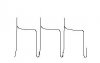
So now, I just got back to my desk from the test bench. The problem is definitely with the SS Relay. I disconnected the relay and my o-scope showed me a beautiful, perfect 14.5V square wave. This was unexpected as I thought my input was only 6V so I checked the input and it too was 14.5V. So I am concluding that the relay is sucking some major amperage. Luckily, my chip didn't burn like the last 5 or 6.

I reconnected the relay and disconnected the timer and got the same 3V square wave as before. So the timer doesn't seem to add any to the problem.

This test was done without being connected to the actuator.

Still looking for help :confused:
 
My guess is that your relay is shot, or you've connected it incorrectly. What is the voltage of the actuator? Is it AC or DC?
 
My guess is that your relay is shot, or you've connected it incorrectly. What is the voltage of the actuator? Is it AC or DC?

The actuator os 115V, 400Hz

I have a backup relay so connecting another one up won't be a problem. I will try that and report back...
 
Last edited:
I think you're going to have another problem with your design. The data sheet says this relay is "zero switching." If I interpret that correctly, you will possible have as long as 1.25mS from the time you send the signal, until you have switching at the output. ( 800 zero crossings per second => 1.25mS between crossings )

You're error thus is: 1.25/37 = 33.8%

Also, the data sheet says the output is for 50/60 Hz. Not sure how well it will work @400Hz.

Oops, that should be 3.38% error. Sorry.

I think I could tweak out the switching delay on the chart. Right now I would just be happy with a working circuit.

Could you please direct me to the data sheet? I couldn't find anything in the data I was given abouut the frequency of the output. Thanks!

I changed out the relay and left the output open (not connected to the actuator or power supply). Turned it on and got a different waveform. It isn't right, but it is different. The wavelength was 4.5 µ seconds at about 4V. It spiked at around 7V.


What do you think?
 

Attachments

  • waveform.JPG
    waveform.JPG
    3.9 KB · Views: 147
I still don't understand why the output drops from 14.5V to 4V when the relay is connected. The spikes just look like inductive switching spikes to me. The datasheet is given below

Maybe someone else has an idea???**broken link removed**
 
It is not an NE555, it is a low power TLC555 which is a Cmos one.

It has a 1k resistor in series with its power supply pin. Why???
Then its supply voltage jumps all over the place.

It might get hot when its supply was 12V because it might be a "factory reject" sold by RadioShack. Its max recommended supply voltage is 15V when it should be cold.
 
Why indeed!? I missed that on the drawing.

hi dwhitt,
I deleted that resistor from the circuit I reposted.

Ref the +15V supply to your project, what is the source of the +15V.?
 
I still don't understand why the output drops from 14.5V to 4V when the relay is connected. The spikes just look like inductive switching spikes to me. The datasheet is given below

Maybe someone else has an idea???**broken link removed**

Thanks for the link!

It is not an NE555, it is a low power TLC555 which is a Cmos one.

It has a 1k resistor in series with its power supply pin. Why???
Then its supply voltage jumps all over the place.

It might get hot when its supply was 12V because it might be a "factory reject" sold by RadioShack. Its max recommended supply voltage is 15V when it should be cold.

Originally we had it connected directly to the 15V supply but like I said, my chips were burning up and after burning 4 of them I added the resistor to the power supply to step down the voltage. I don't think it was a factory reject because of so many of them having the same problem, unless of course, I have a knack for picking up rejected chips.

Does it matter that it is a CMOS version? The packaging said it was the same as the NE555??? We are in a small town without a good electrical supplier. That was the best I could find in short notice. But if the consensus is to change the chip then I will order the *right* one online. My boss is just in a hurry for this to be done if you know what I mean.

hi dwhitt,
I deleted that resistor from the circuit I reposted.

Ref the +15V supply to your project, what is the source of the +15V.?

I purchased a 115VAC~15VDC converter that plugs directly into the wall.
 
Now the low power Cmos 555 is trying to drive a base resistor for the transistor that is only 220 ohms. Why???
The 220 ohm resistor is trying to draw (15V - 0.7V)/220 ohms= 65mA but the low power Cmos 555 has a max output high current of only 10mA when its supply is 15V.

The solid state relay has an input current of only (15V - 1.3V)/1.5k ohms= 9.1mA so the transistor and its base resistor are not needed.
The solid state relay does not use an inductor so the diode across it is also not needed.
 
Measure the 15VDC wall warts output. It's probably higher than you think if only a light load like the 555 is connected.
Are you referring to the output of the transformer? I measured that and it was about 15.4V DC

Now the low power Cmos 555 is trying to drive a base resistor for the transistor that is only 220 ohms. Why???
The 220 ohm resistor is trying to draw (15V - 0.7V)/220 ohms= 65mA but the low power Cmos 555 has a max output high current of only 10mA when its supply is 15V.

The solid state relay has an input current of only (15V - 1.3V)/1.5k ohms= 9.1mA so the transistor and its base resistor are not needed.
The solid state relay does not use an inductor so the diode across it is also not needed.

I actually don't have the transistor logic connected. I still have the first schematic I posted (see here)
https://www.electro-tech-online.com/threads/question-re-ne555-pulse-generator.95066/#post762922
 
Last edited:
Thanks for the bump. :)

No the original circuit was not modified other than changing out the relay. According to Audioguru the transistor, base resistor, and diode are not needed.
 
Thanks for the bump. :)

No the original circuit was not modified other than changing out the relay. According to Audioguru the transistor, base resistor, and diode are not needed.

OK,
So what stage and state is the project currently at.?
Do you require any more input from us.?:)
 
I am still having the same problem with the voltage drop from the input to the output of the 555 chip when the relay is connected. The input is about 6.5V and the output is about 4V.

I guess I am still looking for ideas on how to correct this. It seems I am getting conflicting information regarding adding the transistor and diode circuitry. I have the transistor but don't want to solder it on until I am fairly sure that this will work.
 
I am still having the same problem with the voltage drop from the input to the output of the 555 chip when the relay is connected. The input is about 6.5V and the output is about 4V.
That is normal. You have a 1k resistor in series with the power to the circuit so the supply voltage of the C555 is jumping up and down.
Also the Cmos 555 has a very low output current so it has a high output voltage loss.

Don't you still have a solid-state relay with a minimum input voltage of 3V?
 
Status
Not open for further replies.

Latest threads

New Articles From Microcontroller Tips

Back
Top