I am still having the same problem with the voltage drop from the input to the output of the 555 chip when the relay is connected. The input is about 6.5V and the output is about 4V.
I guess I am still looking for ideas on how to correct this. It seems I am getting conflicting information regarding adding the transistor and diode circuitry. I have the transistor but don't want to solder it on until I am fairly sure that this will work.
hi DW,
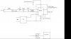
Look at this circuit.
The 100R and 12Vz will reduce the voltage to the NE555 to 12V
What is the electrical spec for the counter.??
Are you using a TLC555 CMOS or NE555 TTL
Attachments
Last edited:
")
")
 I did make the correction in my schematic in regards to the naming of the chip.