Continue to Site

Welcome to our site!

Electro Tech is an online community (with over 170,000 members) who enjoy talking about and building electronic circuits, projects and gadgets. To participate you need to register. Registration is free. Click here to register now.

  • Welcome to our site! Electro Tech is an online community (with over 170,000 members) who enjoy talking about and building electronic circuits, projects and gadgets. To participate you need to register. Registration is free. Click here to register now.

Question about 6v lead acid battery charger circuit

Status
Not open for further replies.

sazzad7

New Member
Question about 6v lead acid battery charging status indicator circuit

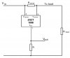
If i want to design a charging status indicator circuit for 6v lead acid battery then which rating zener diode should i use?
And what is the over charged voltage value for 6v lead acid battery?
For example : if i use 6.8v zener diode then it will work when battery gives 6.8+ 0.7= 7.5v cause zener diode has internal voltage drop of 0.7v. Am i right?
Can anyone tell me that plz?
 
Last edited:
A lead acid battery charger is far, far more complex than what you can achieve with a zener shunt regulator. It is a multi-step process.

You may want to read the following:
 
Last edited:
Sorry, i made a mistake. . .actually i want to know about charging status indicator circuit. Post is edited. Thanks
 
... i want to know about charging status indicator circuit... Thanks
Determining State of Charge by reading battery voltage is about as useful as reading tea leaves.

Tell us what you expect it to tell you? Is the battery under load? Completely isolated? Under charge?

Are you trying to build a low-battery alarm? Auto load disconnect? What?
 
I want to make a circuit which lights up a led when the 6v battery is fully charged. So i need to know what is the value of the voltage of 6v battery when it gets fully charged. And which value of zener diode should i use?
 
If you had read the references we provided you, you would understand that there is no magic voltage that says a battery is "charged".

A lead-acid battery is fully charged when the current it draws from a constant-voltage charging source drops to a few tens of mA while the battery terminal voltage is held at 2.4V per cell (7.2V for a three cell battery).

At the point the battery first reaches 7.2V during charge, it is NOT fully charged; not even close.
 
Like MikeMl said:

"A lead-acid battery is fully charged when the current it draws from a constant-voltage charging source drops to a few tens of mA while the battery terminal voltage is held at 2.4V per cell (7.2V for a three cell battery)."
 
can you tell me what will be the zener diode rating if i use this circuit for 6v battery? . . . .
 

Attachments

  • indicator_png.png
    indicator_png.png
    9.1 KB · Views: 316
Last edited:
Tried to open your attachment, but it gave me the following error message:

"Invalid Attachment specified"

If you are attempting to upload an image, then it must be in the .JPG .GIF or .PNG format
 
Like ST said, your link in post #10 doesn't work. So there is no way to tell you what zener to use if we don't know the circuit.

And, like Mike has said, a lead acid battery is NOT fully charged when it reaches a certain voltage. You need to monitor the CURRENT.
 
Zetex **broken link removed** and its bretheran
 
Hello there,


Some nice links in this thread.


Charging Lead Acid is relatively simple. More simple than charging NiMH for example. But even though it's simple, you should use a circuit that can do it right. You can ignore the 'float' charge phase of this because that is only necessary when you want to keep a battery fresh over time when it's not being used. If you really need that, only then would you need to incorporate that too.

The basic idea is to use a voltage limited power supply that is also current limited. The current limit is set to less than the max the battery can take according to the manufacturer's specs for that battery. The voltage limit is set by the number of cells. To get a circuit like this requires a few components that are not expensive.

For example, using an LM317 set to around 14.2 volts (for a 12v battery, half that for a 6v battery) and using a simple current limiting resistor on the input, you can charge a LA battery (under 1.5 amps charge current). But a zener diode shunt regulator (which looks like what you have shown) is not the way to do it. A series regulator is the way to do it, and it's not a great idea to use a zener when there are many better methods to get that right voltage.

So i guess the question then is, have you ever used a LM317 and if not would you want to try this? Also, what is the ampere hour rating of your battery? (this is important too)

Current limiting is simple enough when you use a small series resistor to measure current, or even just a simple series resistor sometimes will work when the power supply output voltage is relatively constant. With the LM317 you can use a series resistor if the required max charge current isnt too high, like maybe around an amp. Adding active current limiting isnt hard either though, a small transistor and a couple resistors and you have your current limit.

One thing to remember is that charging LA is like charging Li-ion, you need a voltage and current limited supply, but the voltage output tolerance has to be more accurate than the current limit. The current limit can be done with a small transistor and resistors and doesnt have to be accurate at all. For a 1 amp current limit, if it was actually 0.8 amps to 1.2 amps it would still be ok for example, but the voltage needs to be fairly accurate, within a few percent. And also if you charge at other than room temperature you may have to adjust the voltage a little to compensate for the temperature of the battery.

If you'd like to see a LM317 battery charging circuit i could post one here.
 
Last edited:
As soon as the battery voltage exceeds the point at which the zener conducts in that circuit you will destroy both zener and transistor, because there is no current-limiting resistor in the zener path. For reasons others have stated above there is no zener voltage which would be satisfactory for measuring charge state with such a simple circuit. You need to monitor charge current, not just voltage.
 
Thanks all. . . .thanks to MikeMI, MrAI and alec_t for your valuable comments. Now I'm clear that i have to play with current not voltage . . . . :D .
MikeMI suggest me to use zxct1009 to monitor charging current to know the battery is fully charged or not. I saw the data sheet . Here V(sense) is equal to V(out) and R(out) is greater than R(sense). Am i right? So when battery is fully charged, charging current will be decreased. As a result V(out) should decrease also! If i am right then is there any way to turn ON a led using V(out) when the battery is fully charged (without microcontroller)?
 

Attachments

  • High side current.jpg
    High side current.jpg
    45.7 KB · Views: 270
Here V(sense) is equal to V(out)
No. V(sense) is the voltage dropped across Rsense by the load (charging) current. V(out) is the voltage across Rout by Iout.
R(out) is greater than R(sense)
Probably. But it doesn't have to be.
 
Last edited:
Can any one show me the modified circuit of above image with a led ? Should i connect the led across R(out) or not?
 
Status
Not open for further replies.

Latest threads

Back
Top