Now you have finally given enough info to suggest a circuit.
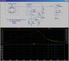
Here is a simulation of a circuit that will light the LED when the charging current into a 3 cell Sealed Lead Acid Battery drops below ~50mA (adjustable with R2). I am assuming that the recharge of your SLA is like shown in the upper plot pane. The red trace shows the battery voltage, starting at 6V (mostly discharged), accumulating charge from 0s to 2000s (33min), at which point the charger stops limiting the charging current at 0.6A and it begins limiting the battery voltage to 7.2V. With the voltage limited at 7.2V charging current (green trace) decreases asymptotically toward the leakage current of the battery. The goal is to light the LED prior to reaching the leakage current of a few tens of mA.
Note that the box in the upper left models the way a proper SLA charger should work(current limited initially, voltage limited thereafter). You will have to determine if your charger behaves this way, or not.
The box in the upper right models the SLA battery, where C1 represents charge accumulation, and R6 represents the battery's leakage, in this case
[email protected]
The box in the center represents a ZXCT1009 high-side current monitor as a voltage-controlled current-source with a trans-conductance of 10000uA/V, which comes right off the data sheet.
R1 is the shunt resistor. The ZXCT1009 converts the voltage drop across R1 into a current that flows to ground. With R1=100mΩ, at 600mA, 600uA flows out of the bottom terminal of the ZXCT1009 turning on Q1. As this current decreases, R2 (the adjustable pot) sets the trip voltage for the Schmitt trigger consisting of Q1 and Q2, providing a bit of hysteresis and a snap-action turn-on of the LED.
Refer to the lower plot pane. This shows the current through the LED as a function of time at four different values of R2 (5K, 10K, 15K, and 20K, left to right). You can adjust how low the charging current drops before the LED turns-on. I would use around 15K.
A couple of other thoughts... The obvious improvement is to use the LED-switching to also either shut off the charger (since 7.2V is
too high a voltage to float the battery at indefinitely), or to switch the voltage regulator in the charger from 7.2V to 6.6V (at which point the battery
can be floated indefinitely). I have build similar automatic chargers for 14V batteries, and this is what is termed a three stage automatic charger: Initially current limited, then voltage limited at the higher charging voltage, then automatically switching to a lower float voltage. Since you can now buy these ready-made for ~$25, I have stopped building them