Continue to Site

Welcome to our site!

Electro Tech is an online community (with over 170,000 members) who enjoy talking about and building electronic circuits, projects and gadgets. To participate you need to register. Registration is free. Click here to register now.

  • Welcome to our site! Electro Tech is an online community (with over 170,000 members) who enjoy talking about and building electronic circuits, projects and gadgets. To participate you need to register. Registration is free. Click here to register now.

Pyranometer interface to Arduino

Status
Not open for further replies.
Hello
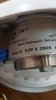
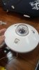
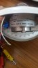
I am working on a circuit connecting a pyranometer and an arduino board, the Pyrano delivers voltages of uV scale ( Sensitivity of 5.41 uV/Wm2) and to make the signal readbale by the arduino it needs to be implified, i started by testing sone amplfiers and i came across AD624 , while simulating my circuit an input of 1mV gave an amplification of 500 mV ( i set the gain= 500) however when i change it to 1uV or 1V the amplification gives unreasonable results knowing that i only used the AD624 a voltage source and a multimeter nothing else attached , what may be the problem ?
 
Did you really expect the AD624 to be able to output 1Vinput x 500gain = 500Voutput when it's only powered from a 15V source?

THe noise in the AD624 also exceeds 10uV which is 10x larger than your 1uV input.

The AD624 is a real component with real upper and lower limitations.
 
And what's the lowest voltage you expect?
A signal with a high dynamic range may require a better ADC than the one built into the arduino. In addition, you might find that you need to switch gain ranges under software control in order to make the best use of the dynamic range of your ADC.
If you are measuring the sun's radiation (I'd never heard of a pyranometer before) then I presume the signal changes only very slowly, so you should be able to filter the amplifier quite heavily to remove quite a lot of the amplifier noise.

Do you have a datasheet for the pyranometer you are using that you could show us?
 
the lowest value i got is around 0.00023 mV and the pyranometer is a kipp&zonen CM11850828 there is only a webpage of the product i guess the one we are using is quite old actuly and my supervioser insistes on using it. I tried to use a simple operational amplifier and transistor based circuit however i get stuck on the quilty of the amplification honestly i can't figure out the circuite i should be using nor the material !!
 
The problem seems to be that you want/require too high a dynamic range with a single gain value. You're going to have to set your expectations though and decide how low and high you actually need from the sensor rather than what it can do.

From the sound of it, 5mV is the maximum output you expect and 230nV is the lowest, but do you actually need a reading this low? 230nV to 5mV covers a dynamic range of 22,000:1 or 87dB. It's not easy to build electronics quiet enough to amplify 230nV. What do you actually need?

The most practical solutions are:

1. Use an amp with variable gain and adjust the gain dynamically according to the level of the input
2. Use a pre-amp that feeds into either:
(a) multiple parallel fixed gain amps and always measure from the the appropriate output for the input level
(b) a single amp that can output 500V (this is probably a bad idea unless you know exactly what you're doing and actually need a 500V output)

Additional things you can do are use a 16-bit ADC, but it takes some effort to keep your circuit board sufficiently low-noise to preserve the 16-bit accuracy. Stay away from 24-bit ADCs...if you don't know that you need one then you don't know enough to properly build a board for one.

A gain of 1000 would let you use the full-input range of a 5V 16-bit ADC and have a resolution one third of 230nV. This is the most difficult possible solution though: Using a 16-bit ADC with a single-stage, fixed gain amp. I'm not certain I could do it myself. I'd definitely scrap at least five 8-layered PCB designs in the process and I'm also pretty sure op-amps chips that work at 230nV run $100+ each. I have a 16-bit ADC that's been sitting at home for a year now that I want to make a PCB for just to see how badly I can get it to it will perform.
 
Last edited:
Just to clarify, I think 230nV was a typo - it's corrected in #9 as 23uV. Easier, but still not trivial!

I'm no design engineer, but I think you are on the right track looking for "instrumentation amplifiers". Although you can build an instrumentation amplifier from single op-amps, as far as I can see this would be a typical application for one of the many purpose built instumentation amplifiers that are available, like the AD634 that you have already mentioned.

For the sake of throwing some ideas about, I think I would do the following:

1. Use an instrumentation amplifier which uses an external resistor to set the gain. In this aplication I think DC acuracy and drift would be your biggest concern, so you can trade off other atributes against these.

2. Use reed relays to switch in different gain resistors under the control of the microprocessor. Design in more gain steps than I think I might need and make it easy to change resistors so the gain steps can be adjusted. Relays are slow, bulky, expensive etc, but I think they should give you the best chance of avoiding noise injection, offsets caused by leakage, gain problems caused by on-resistance, nonlinearities etc. Something of a safe option.

3. Provide some RC filtering on the output of the instrumentation amplifier, but nothing active to avoid introducing any other noise or inaccuracies. This could probably be set quite low in frequency and should remove quite a lot of noise.

4. Use an external ADC (rather than one built into a microcontroller), so that you can select the best one for the job and lay the board out in an optimal manner. I would rather select an ADC with more bits of resolution than I could use than one with too few. That is to say, I'd rather have the amplifier noise determine the dynamic range then the converter resolution.

5. Use software averaging across multiple reads of the ADC to further reduce noise.

6. Have the software compare "before" and "after" readings from the ADC when switching gains, and calculate the gain change of the amplifier from this. This can give you some proof that the amplifer is working correctly, and should allow you to avoid "glitches" in the readings when the gain range switches.

This is just some of my thoughts - I'm sure there are some people more knowlegable than I who'll be able to point out what's wrong here and give some better ideas.
To add, if you do use reed relays make sure it supports dry switching and NEVER use it for wet switching or else you'll have to swap that relay out for a new one since it will be no good for dry switching anymore.
 
As expected - it's always more complicated then it seems!

I know I should probaly jusk ask Google, but for the sake of having it documented here, could you expand upon what is meant by "dry" and "wet" switching?
I presume it's about whether you're switching current or not - I was forgetting that most (all?) mechanical contacts require a minimum current before they will perform as specified.

Dry just means passing practically no current (usually signals). Wet means passing current (usually power). Cuz electrons are like...water, I guess?

It has something to do with currents causing arcing across the contacts of switches and relays when they open. The arcing causes deposits to form on the contacts of relays and switches which can't be broken through by very low current signals. Dry contacts are pretty much always gold plated for similar reasons.
 
Thank you all for your replies it was really helpful, actully a tried some simple manipulations to see the behaviour of the AD624 on a simulation level, and apperently when it is generated by a sin signal it works really good, however at a DC voltage and at a certain level the amplification gets messed up, and since the data we are going to insert to the amlifier is random what do you think will be the solution ?
 
What is the model # of the pyranometer?

I'm unable to find kipp&zonen CM11850828

Got a link?
 
Last edited:
This is the pyranometer i couldn't find any documents either that's the problem i beleive it is a quite old reference anyway i send some phtos in the attached section
 

Attachments

  • 24739940_844334699068374_808399673_o.jpg
    24739940_844334699068374_808399673_o.jpg
    121.1 KB · Views: 143
  • 24740183_844334715735039_1676261938_o.jpg
    24740183_844334715735039_1676261938_o.jpg
    159.1 KB · Views: 148
  • 24819076_844334712401706_1533909407_o.jpg
    24819076_844334712401706_1533909407_o.jpg
    163.9 KB · Views: 125
Thank you all for your replies it was really helpful, actully a tried some simple manipulations to see the behaviour of the AD624 on a simulation level, and apperently when it is generated by a sin signal it works really good, however at a DC voltage and at a certain level the amplification gets messed up, and since the data we are going to insert to the amlifier is random what do you think will be the solution ?
Your random input is still going to be within some expected limits. You are going to have to set a level of gain that is reasonable for what you expect, or use variable gain as described above.

Also, did you realize the AD624 only has a rail-to-rail output of +/-10V when running off 15V?
 
Last edited:
Also, did you realize the AD624 only has a rail-to-rail output of +/-10V when running off 15V?
How does this detail affect my circuit ? as for the data i guess you are right im just concerend since the value at wich the error starts is 0.001 mV
 
Status
Not open for further replies.

Latest threads

New Articles From Microcontroller Tips

Back
Top