Continue to Site

Welcome to our site!

Electro Tech is an online community (with over 170,000 members) who enjoy talking about and building electronic circuits, projects and gadgets. To participate you need to register. Registration is free. Click here to register now.

  • Welcome to our site! Electro Tech is an online community (with over 170,000 members) who enjoy talking about and building electronic circuits, projects and gadgets. To participate you need to register. Registration is free. Click here to register now.

PX26 PRESSURE SENSOR AND AD620aN AMPLIFICATION PROBLEMS

Status
Not open for further replies.
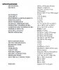
Im using a px26 001GV differential pressure sensor for a project with arduino, here is the data sheet. (https://www.omega.com/manuals/manualpdf/M1608.pdf) Now, I have few questions regarding this.

1) I'm using this around a valve to know the differential pressure, lets say side A and side B Now if side A>B i get a positive voltage in milli volts, what if side B>A would it give a negative voltage? so would I get a range of voltages for its full functionality from negative to positive like say -8mv to +8mv?

2)I'm using an op amp to amplify the reading so I could amplify 8.6mv to 1.8V and then the opamp saturates, is there any way around this?

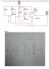
3) the opamp AD620AN which is a instrumental amp to be precise , needs voltage ranges -5 t0 +5 so i used a 10 volts dc, made a voltage divider, created a virtual ground. So what if I connect this system to arduino (0to5V range) would the divider cut off the system to (-2.5 to +2.5)?If so, should I check my circuit by using a 5V Dc and using the divider and check how the opamp responds?

PS: I'm new to this , please try to avoid all the electrical lingo, I wouldn't understand it. Thank you for your effort!
 

Attachments

  • Capture.JPEG
    Capture.JPEG
    33.9 KB · Views: 248
For those with any ideas this is a carry over from this thread.

The output is going to an analog in pin of an Arduino Mega. My suggestion would be to use a dual supply, along these lines:

LT1920 Inst Amp.png


With 10 volt excitation Vout of the sensor 0 to 1.0 PSIG = 0 to 16.7 mV. The idea is to have a gain to convert the 0 to 16.7 mV to 0 to 5 Volts. This will afford the best resolution on the Arduino. The LT1920 I used is the same as the AD620 for all purposes. I covered the problems of using Vref (pin 5) of the AD620 with the needed gain. The AD620 data sheet in figure 38 shows a single ended supply configuration using Vref. Problems among other things is the Arduino does not have a differential input. Also with .0167 volts to get 5.0 volts the Gain will be about 300. I believe this will afford the best resolution and help with noise. The analog Vref could be changed on the Arduino I guess. However, the AD620 output will still be offset by any Vref on pin 5 other than 0 volts (ground).

Anyone have any ideas or thoughts to share? Read the other thread for more information.

Thanks
Ron
 
Thanks for this, I have few questions on this, when i tried to give the ref to the ground it had problems amplifying unless it was dual sided. is this dual sided, sorry i'm just learning all this, its kinda new to me.

And also since the sensor i use is a differential sensor i've been told that it produces voltages -mv to mv ( considering pressure on both sides) So how does this effect the amplification,
Like I said I've been using a voltage divider to produce mV as input to testthe circuit on bench, is there anyway to produce -mV voltages? or would it just work fine I mean a patriclar pressure has a relative voltage reading no matter what side the pressure is from like side A or side B.


I would like to appreciate your effort in helping me understand this. Thank you ron :)
 
Yes, I used a dual supply to make things simple and what I felt was the best approach. Cosel USA and a host of others manufacture small on board DC to DC switch mode power supplies which are inexpensive, 12 VDC in and +/- 15 VDC out would be idea as a dual supply. Also in my drawing I omitted the decoupling capacitors, you want a .1uf cap on the AD620 power pins to common. Right at the power pins. As drawn because I tie the -IN to Common the amp won't amplify a negative input. As I mentioned in the other thread the Arduino won't take a negative input anyway, not keeping things simple anyway. The Arduino also has input protection for negative inputs. However, a clamping diode could be placed at the AD620 output which would clamp anything negative at about .6 Volt. When setup the sensor should not see a negative pressure so it shouldn't matter.

Maybe someone else has some thoughts?

Ron
 
The single sided approach ought to work.

Then if you want differential voltage choose V/2 as your null pressure value from the ADC.

Choose Vref in the OA (pin 5) to supply V/2 out at null pressure. The Arduino may have a Vref to use that is stable.
 
Yes, I'l try to power it externally that will be a good idea like you said.

one thing i was still trying to figure out is that the differential pressure sensor according to its data sheet says +-16mV, so it would give me +16 or -16mV voltage readings based on the pressure change right?. So is there any way to simulate a say something -8mv and see how its amplified? like i was saying i could simulate a positive mV to check my amp settings, how do i check -8mV?

what my understanding was, even if the signal is negative the op amp would still show me same reading that's for +8mV and -8mV , i mean to say each mv has a multiplied by certain gain used, and the negative and postive are just what sides of the differential pressure measured, but nothing to do with voltages.
is this right?

Thanks & Regards
 
I tried to power it externally using a dual side, ( I have only a single side Dc in my lab so made a voltage divider to create virtual ground)
 
If you only want to measure unipolar pressure then 0~5 for 0~1psi (relative to atmosphere 15.6psi)
If you want to measure -1 to +1psi for 0~5V then you null at 5V
Gain depends on above.

For info on differential amps for a different gage but in same range except yours will be 10V
https://www.ti.com/lit/an/slyt144/slyt144.pdf

I suggest you ask factory for amplifier circuit.
 
upload_2015-3-16_17-40-30.png


I increased the input to 15 volts, and the voltage divider splits it into 2 -7.5 +7.5 and then I get full amplification I require ( 0 to 16mv) , but I dunno how arduino would take this.
 
Somewhere in another thread I believe you mentioned the Arduino was an Arduino Mega?

The Arduino board contains a 6 channel (8 channels on the Mini and Nano, 16 on the Mega), 10-bit analog to digital converter. This means that it will map input voltages between 0 and 5 volts into integer values between 0 and 1023.

So if the Arduino uses a 5V reference for the A/D conversion you get what you see above. Back in post #2 I show a circuit that will give you the correct gain so the bridge output works out 0 to 1 PSID = 0 to 16.7 mV = 0 to 5 Volts. Then you write your code accordingly. If you try to input 16mV into the Arduino Analog Input yoou will get garbage trying to resolve it beccause of noise and the low signal level which is why an instrumentation amplifier is used. So what is the problem?

Ron
 
arduino mega 2560,
I'm using simulink,
I'm using voltage diff of 15(-7.5 to +7.5) where i get required amplification range before the amp saturates, while arduino works with only 0-5v. wouldnt that be a problem.
 
Last edited:
arduino mega 2560,
I'm using simulink,
I'm using voltage diff of 15(-7.5 to +7.5) where i get required amplification range before the amp saturates, while arduino works with only 0-5v. wouldnt that be a problem.

No, why would that be a problem. The Arduino is only seeing 0 to 5 volts on an analog input channel. As long as the Arduino only sees 0 to 5 volts and then you scale the Arduino for engineering units (o to 1.0 PSID) there won't be a problem.

You are powering the Arduino using a 5 volt supply correct? Can you provide a drawing of exactly what you have and are doing?

Ron
 
OK, I used an Arduino Mega and here is what you will have. The code is very basic and the monitor shows the results of the code.
Code:
/*
  AnalogReadSerial
  Reads an analog input on pin 0, prints the result to the serial monitor.
  Takes the reading and converts to engineering units PSID.
  Connect output od Instrumentation Amp to pin A0. 0 to 5 Volt Input.
*/

// the setup routine runs once when you press reset:
void setup() {
  // initialize serial communication at 9600 bits per second:
  Serial.begin(9600);
}
// the loop routine runs over and over again forever:
void loop() {
  // read the input on analog pin 0:
  int sensorValue = analogRead(A0);{
  // print out the value you read:
  float voltage = sensorValue * (1.0 / 1023.0) - 0.01 ;
  // Convert the analog input reading 0 to 1023 to
  // PSID

  Serial.print("Channel 0 = ");
  Serial.print(sensorValue);
  Serial.print( "  ");
  Serial.print ("Bits");
  Serial.print( "  ");
  Serial.print(  voltage);
  Serial.print ("  PSID");
  Serial.println();
  delay(500);  // delay in between reads for stability 1/2 second
}
}

Here is what the above code will yield:

Arduino Monitor.png


I am applying 2.5 volts to the Arduino Channel 0 analog input. You need to keep in mind that micro-controllers like the Arduino are not precision measuring devices. They are 10 bit A/D converters and not very accurate. For example with a 0 to 5 volt input and a 10 bit A/D I should see 0 to 1023 bits and with 2.5 volts applied I should see about 512 bits displayed. This particular chip is showing about 523 bits. That creates an error. I correct that error in the code where you see:

float voltage = sensorValue * (1.0 / 1023.0) - 0.01 ;
I subtract .01 from my conversion to PSID.

Using the PSID reading of 0 to 1.0 you will apply your delta flow math equation. When doing this you need to remember that when doing flow calculations based on flow across an orifice that the actual flow is not linear and is square law in response.

Finally, you can't just use a voltage divider to power the AD620 Instrumentation Amplifier. You need a dual supply to provide a + and - voltage with the ground 0 reference, exactly as I drew it earlier. Not if you want this to work accurately anyway.

I placed the conversion code on the Arduino only as an example. You may want to merely import the 0 to 1023 bits and do the conversion in your own software.

Ron
 
Yay! :)

There you go.

Ron
 
Hi, im trying to calibrate a pressure sensor. Trying to relate the voltage output to a pressure applied.
the sensor im trying to use is px26 001DV, differential pressure sensor. Any thoughts about this procedure.
thanks :)
 
Hi,
I'm new using electronic circuits and stuff related, there are few terms i dont understand, I thought i'd would be better if someone gives me a small explanation on each of the parameter , what it means in the following list.
Following is an attached copy of Omega PX 26 001DV differential pressure transducer

Thanks & REgards
 

Attachments

  • Capture.JPG
    Capture.JPG
    83.4 KB · Views: 184
I see 23 different specifications. How about telling us which you are having trouble with so we can narrow it down a bit.
 
Status
Not open for further replies.

Latest threads

Back
Top