Continue to Site

Welcome to our site!

Electro Tech is an online community (with over 170,000 members) who enjoy talking about and building electronic circuits, projects and gadgets. To participate you need to register. Registration is free. Click here to register now.

  • Welcome to our site! Electro Tech is an online community (with over 170,000 members) who enjoy talking about and building electronic circuits, projects and gadgets. To participate you need to register. Registration is free. Click here to register now.

amplifying px26 pressure transducer with AD 620 op amp, calibration

Status
Not open for further replies.
Hi,

I'm new to circuits and electronics have no basic understanding prior to this project, please forgive my ignorance asking these basic questions and help me.
For my project I have to use a px26 001 DV (differential) omega pressure transducer to find out the pressure in a flow, as you know px26 works in millivolts. I use arduino and matlab to collect data. Arduino cannot detect something in milli volts, hence i have to amplify the sensor output. I have learnt that I could do this using Ad620 instrumentation amp.
So, ,me being new to all this, I'm having problems using the instrumentation amp..
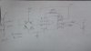
1) Where do i check my amplified voltage is it port 6? Vout?
2) I'm trying to amplify the voltage from 16 milli volts to about 3.2 volts(something that arduino is comfortable with) so I have used an Rg of 400 ohms. is it correct?
3) Can someone tell me the calibration procedure for this pressure sensor? I have been to about shunt calibration using a voltage divider as a reference and comparing those values to the opamp+pressure sensor circuit. What values should i compare, this is quite confusing.
I have to have this amplified voltage fed into the arduino board which connects to matlab simulink .

I have attached a circuit that I'm trying to understand.

Thanks & Regards
 

Attachments

  • Capture.JPG
    Capture.JPG
    51.9 KB · Views: 663
Last edited:
Pin 6 is the Vout of the AD620 Instrumentation Amplifier but it is hard to answer your questions because the PX26 Pressure Sensor is a series of sensors. You make no mention of which one you are using so nobody knows the pressure range. Not knowing the pressure sensor range makes it difficult to know what gain to use on the instrumentation amplifier.

For Example I use a PX26-100GV 0-100 PSIG which is a 0 to 100 PSIG range and the output sensitivity is 10mV/V so for each volt of excitation my full scale output is 10 mV. I will use 10 Volts Excitation so my full scale sensor output is 100 mV for 100 PSIG. Let's say I want my 100 PSIG full scale output to be 5 Volts. 5 Volts / 100 mV = 50 so I need a gain of 50. Looking at my AD620 Data Sheet for a Rgain of 50 I need about a 1K resistor. Rgain can be a fixed resistor in series with a variable resistor so the gain can be calibrated to be accurate with the sensor. I can apply 100 PSI to my sensor and adjust my Rgain for a 5 Volt out from my instrumentation amplifier. From there it's a matter of writing the code to scale the engineering units (PSIG).

Ron
 
The AD620 is an instrumentation amp, not an op amp (look at the data sheet title).

1) Yes, pin 6 is the output. (I see no purpose for the pot at the output going to +5V. What's that supposed to do?)

2) You need a gain of 200 to amplify 16mV to 3.2V. The gain resistor Rg for the AD620 is calculated as 49.4kΩ / (G-1) where G is the gain. This gives Rg = 248Ω.

3) To calibrate the pressure sensor you need a known accurate pressure source. Do you have that?
 
2) I'm trying to amplify the voltage from 16 milli volts to about 3.2 volts(something that arduino is comfortable with) so I have used an Rg of 400 ohms. is it correct?

I missed that which Carl obviously didn't. :) I also missed the 3.2 Volts. :(
(16.7mV, 1.67mV/V for
1 PSI range)
So you have a 1.0 PSI Sensor correct? Therefore your sensor full scale output is 16.7 mV with 10 Volt excitation applied. Just set the gain as Carl has covered.

Ron
 
Mine is px26-001 DV 0-1 PSIG.
I don't have an accurate pressure source.
What if I use 5V instead of 10V input, and increase gain to 400 , its amplifies to 3.2 v right?
 
Mine is px26-001 DV 0-1 PSIG.
I don't have an accurate pressure source.
What if I use 5V instead of 10V input, and increase gain to 400 , its amplifies to 3.2 v right?
Reducing the voltage and increasing the gain tends to increase the error in the reading.

If you don't have an accurate pressure source then what do you mean by "calibration" of the sensor? :confused:
 
I'm trying to hook it up to my arduino mega 2650 connected to Matlab simulink find the pressures in a pipe flow. Matlab shows bit valves between 0-1023 based on the voltages, so I want to relate these voltages and bit values to set up a feed back system that would read the pressure in the pipe.
I have been told that px26 had no enough output for the 2560board to read, hence told to amplify the reading using AD620.

So right now I'm having problems with the circuit connected and having the voltage amplified.

what values should go into -In and +In
I konw +Vs -Vs has the voltage source connected through a function generator.
And pin 1/8 has a gain of 400 ohms, 6 being the output.( where the amplified gain is noted)
I do not know where ref goes.

Sorry for ask so many questions, this is very new to me and pretty confusing.

Thank you very much for all your effort and patience.
 
First, as to your calibration and achieving 1.0 PSIG. Give this article a read as it is based on an Arduino but would work with any pressure sensor. While the article focuses on measuring level in a tank if the level is known the pressure can be calculated. I place a tube within a larger diameter tube and place a cap on the larger tube and fill it with water. If I insert my small diameter tube into the water and down, then blow into the small tube as I push water out of the tube using air pressure the required pressure to get bubbles to escape the bottom of the tube is proportional to the the water level in the tube. If I take a large diameter PVC pipe and cap one end, my pipe is 36" tall (3 foot section of pipe) and place a ruler in it or beside it (clear pipe) then fill it to 27.68" of water (26.7" is close enough) you can figure when my narrow tube bubbles I am applying 1.0 PSIG. Short of an elaborate calibration system that will get you an accurate 1.0 PSIG or less with less water level. 6.9" water = 0.250 PSIG, 13.8" water = 0.5 PSIG, 20.8" water = 0.750 PSIG and 27.7" water = 1.0 PSIG.

That said and as Carl points out, when you start using lower excitation voltages you gain needs increased and your accuracy suffers. This is not a good practice. Also, you want the reference voltage to be as stable as possible. Any drift in the excitation voltage will reflect in the mV/V output of the bridge and then be amplified by the instrumentation amplifier. This is where it is wise and good practice to use a stable 10 volt reference for the bridge excitation. A Google of 10 Volt Reference will bring up a dozen hits similar to the link. If you want to accurately measure and resolve 1.0 PSIG you really want good stability.

As to the Reference terminal:

REFERENCE TERMINAL
The reference terminal potential defines the zero output voltage
and is especially useful when the load does not share a precise
ground with the rest of the system. It provides a direct means of
injecting a precise offset to the output, with an allowable range
of 2 V within the supply voltages. Parasitic resistance should be
kept to a minimum for optimum CMR.

For your application reference gets tied to ground. See the AD620 data sheet. Also the +VS (Positive Vsupply) and -VS 9Negative Vsupply) are your power for the instrumentation amplifier. I do not understand the reference to a Function Generator? This is the data sheet for the AD620, have you read it and looked at the examples? Pin 6 the output would go to your uC (Arduino Analog Input).

Ron
 
HI,
I have changed my circuit , it now works amplifying the input.
I simulated millvoltages by using a voltage divider.
so for a 3.5mv input i could output it to 0.79V
for a 8.5 it goes to 1.823V
and then the instumental amp Saturates, Is there any way to increase this.

2) And also im using a differential pressure sensor for sensing a flow over a valve of sides A and B, if you know anything about them, what if i have a negative pressure I mean if A> B gives me a positive voltage , what if B>A and what kind of voltage value should i anticipate. I don't really know much of electronics I'm trying to read up as much as I can.
 
I don't believe the AD620 is a rail to rail instrumentation amplifier. What are you powering the AD620 with, what is the +Vs and -Vs? For example if the AD620 is powered by 3.3 volts the highest Vout will be +Vs - 1.2V = about 2.1 V and I say about as it can vary chip to chip. This is called Output Swing in the data sheet. The only way to increase Vout is to increase +Vs for a single supply configuration. What +Vs are you using?

what if i have a negative pressure I mean if A> B gives me a positive voltage , what if B>A and what kind of voltage value should i anticipate.

I am not sure how the sensor will handle differential pressure? Some sensors like many I worked with would, by design, output a negative voltage which in this case the instrumentation amplifier unless using a dual +/- supply won't process. The only times I saw negative numbers on my flow meters was when the pump was off and water in the lines (weight of the column of water) would show a few GPM of negative flow. Since in your case the IA can't go negative I do not see much of anything happening. Finally, short of additional circuitry your Arduino Mega using the analogRead() returns a number between 0 and 1023 that is proportional to the amount of voltage being applied to the pin.

Ron
 
I made a voltage divider for 0 to 10 and made a virtual ground for ref, so Vs+ is +5 and ref (pin5) is given to the virtual ground and Vs- to the 0 which acts as -5V.
 
OK, looking at your numbers :
so for a 3.5mv input i could output it to 0.79V
for a 8.5 it goes to 1.823V
3.5mV to 0.790V becomes .79/.0035 = 225.714 Gain
8.5mV to 1.823V becomes 1.823 / .0085 = 214.470 Gain

Something isn't right as the gain linearity should be much better than what you are seeing. You are measuring all of this with a good meter referenced to ground (common) correct?

Ron
 
I think I see where the problem(s) may be. The following is taken from a data sheet for another instrumentation amplifier which is pretty much identical to the AD620:

Single Supply Operation
For single supply operation, the REF pin can be at the same
potential as the negative supply (Pin 4) provided the
output of the instrumentation amplifier remains inside the
specified operating range and that one of the inputs is at
least 2.5V above ground.

The other chip was an Analog Technologies LT1920.

Now looking at the AD620 data sheet Figure 38. A Pressure Monitor Circuit that Operates on a 5 V Single Supply. Note how the low bridge voltage is handled and how pin 5 is used. I believe to use the AD620 as we wish to use it you will need a dual supply. Either a dual supply or configure your amplifier as shown in Figure 38 of the AD620 data sheet. Hopefully Carl or another member will confirm this.

Ron
 
Yes, it needs a dual voltage , thats why i connected the ref to a voltage divider( 0 to 10 v) making it +5 -5 thus ref at 0 ( virtually)
i measured the gain its 216.9 to be precise. I rounded up the values while positng , sorry do you wanna know the actuall values?
 
I think I know the problem. Let me build the circuit and simulate it. I'll get to it in the morning.

Ron
 
I posted in the other thread also. More in the morning and hopefully someone else has some thoughts.

Ron
 
Status
Not open for further replies.

New Articles From Microcontroller Tips

Back
Top