Continue to Site

Welcome to our site!

Electro Tech is an online community (with over 170,000 members) who enjoy talking about and building electronic circuits, projects and gadgets. To participate you need to register. Registration is free. Click here to register now.

  • Welcome to our site! Electro Tech is an online community (with over 170,000 members) who enjoy talking about and building electronic circuits, projects and gadgets. To participate you need to register. Registration is free. Click here to register now.

push pull balance B class

Status
Not open for further replies.

mif_tronics

New Member
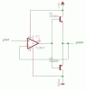
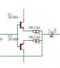
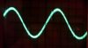
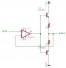
i had tried to make an AC buffer so i used the B class push pull circuit. but i didn't find a crossover distortion when i coupled both transistor (NPN & PNP) straightly. theorytically, it should be a distortion there because of forward biasing emitter diode (in both transistor). i used 2N3904 and 2N3906, then i put two 330 ohm resistors on each emitter tap. i got a pure sine wave on 40 KHz. i dont know why there's no distortion, but i should explain it on my final project book.
 

Attachments

  • circuit.JPG
    circuit.JPG
    4 KB · Views: 385
The cross over is there. You're just not seeing it. Take a look at this (attached):

Here, you see the output of a vacuum tube amp I designed and built subtracted from the input signal with a differential amp. The residual is a sine due to phase shift. Here, you can see the switching glitches caused as one VT in a push-pull pair cuts off. The mode here is Class AB1. If you o'scope the output alone, you don't see these glitches since they are so small relative to the output.

If you were to do the same, subtract the input from the output and null the difference as much as possible, you'd see plenty of cross-over distortion. If you hooked up a small speaker, you could hear it. Cross over sounds really nasty.
 

Attachments

  • 166Hz-renard.jpg
    166Hz-renard.jpg
    16.5 KB · Views: 365
You've only shown us the output stage, are there more transistors or an op-amp on the input stage?

Is there any negative feedback?


Another thing, those emitter resistors aren't required on a class B amplifier as there's no chance of thermal runaway occuring because the two transistors are never biased on at the same time.
If so it could be enough to almost totally eliminate the crossover distortion.
 
push pull

does it mean that i shouldnt use the diode biasing one? b'cause i dont use it on an audio purpose, i just use it to couple an wien bridge osc to a ultrasonic tranducer so that the frequency doesnt getting lower when i coupling them.
i also use it to get an perfect saturation voltage from an op amp comparator when coupling it to an active filter.
 
What diodes?

There are no diodes in your schematic.

I don't know what you're talking about, please post the full schematic.
 
That's a class A-B amplifier (depending on the voltage drop of the diodes) and requires emitter resistor resistors to be fitted.

The biasing resistors should allow 1/10 of the output current to flow for the amplifier to work properly.
 
in what value the R is?

You've now left out the emitter resistors, which are absolutely essential in that (very poor) circuit.

For your purposes (driving an ultrasonic transducer) the first one was absolutely fine, crossover distortion isn't a problem in that application, and you won't be running at tiny volumes anyway.
 
can i use my first scheme when driving an analog butterworth filter?
what bout using an op amp as amp input ? is that better than the first one?
 

Attachments

  • opamp pushpull.JPG
    opamp pushpull.JPG
    14.5 KB · Views: 485
As I said before, you don't need any emitter resistors for a class B amplifier. Emitter resistors are only required for class AB and class A designs.

You haven't connected the power supply pins to your op-amp so it won't work.

Here's the circuit with the emitter resistors removed and the power supply connections to the op-amp.

What's the impedance of the transducer?

The lowest impedance this circuit can drive is about 200:eek:hm:.
 

Attachments

  • Op-amp Booster.GIF
    Op-amp Booster.GIF
    11.4 KB · Views: 608
Last edited:
Hi,

Currently i am trying to build Class AB Amplifier.
I am stuck with calculating theoratically the biasing and emitter resistors.
Could you please guide me how i should calculate.

I have just simulated the circuit, it is working well. but i need to calculate with formulas.
Many thanks in advance.

Details from simulation:

Biasing Resistors - 499 and 499 Ohms
Emitter resistor - 2 and 2 Ohms
Transistor - TIP35C and TIP36C
Diodes - 1N4148
Power Supply - +12 and -12V
Load resistance - 0.5 Ohms
Input - Sin wave 5 Volts
Output - 5 Volts
Current - 1.25 Amps
 
Last edited:
Currently i am trying to build Class AB Amplifier.
But you provided no details:
1) Is the 5V output 5V RMS? 5V peak? 5V peak-to-peak? Then the output current into the 0.5 ohm load is many Amps.
2) I guess the 1.25A output into the 0.5 ohms load means the output voltage is not anywhere near 5V.
3) Why is the load almost a dead short? Most speakers are 8 ohms.
4) Why are the emitter resistor values way too high so they throw away most of the output power?

At the max output voltage swing, calculate the output current. See the datasheets for the transistors ands see the minimum current gain (hFE) at the max output current and divide to find the max base current. Use Ohm's Law to calculate the base resistor values.
 
Status
Not open for further replies.

New Articles From Microcontroller Tips

Back
Top